Electrical equipment VAZ 2107: design, principle of operation and connection diagrams
Content
- Design features of the on-board network VAZ 2107
- On-board network systems VAZ 2107 and the principle of their operation
- The main malfunctions of electrical equipment VAZ 2107
The operation of any automobile engine is impossible without the appropriate electrical equipment. And if we consider the car as a whole, then without it it is just an ordinary cart. In this article, we will look at how the on-board network of a car is arranged and works using the VAZ 2107 as an example.
Design features of the on-board network VAZ 2107
In the "sevens", as in most modern machines, a single-wire circuit for supplying electricity to electrical equipment is used. We all know that the power to the devices is suitable only for one conductor - positive. The other output of the consumer is always connected to the "mass" of the machine, to which the negative terminal of the battery is connected. This solution allows not only to simplify the design of the on-board network, but also to slow down electrochemical corrosion processes.
Sources of current
The car's on-board network has two power sources: a battery and a generator. When the car's engine is turned off, electricity is supplied to the network exclusively from the battery. When the power unit is running, power is supplied from the generator.
The nominal voltage of the G12's on-board network is 11,0 V, however, depending on the operating mode of the motor, it can vary between 14,7–2107 V. Almost all VAZ XNUMX electrical circuits are protected in the form of fuses (fuses). The inclusion of the main electrical appliances is carried out through a relay.
Wiring of the on-board network VAZ 2107
The combination of electrical appliances into one common circuit of the "seven" is carried out by means of flexible wires of the PVA type. The conductive cores of these conductors are twisted from thin copper wires, the number of which can vary from 19 to 84. The cross section of the wire depends on the strength of the current flowing through it. The VAZ 2107 uses conductors with a cross section:
- 0,75 mm2;
- 1,0 mm2;
- 1,5 mm2;
- 2,5 mm2;
- 4,0 mm2;
- 6,0 mm2;
- 16,0 mm2.
Polyvinyl chloride is used as an insulating layer, which is resistant to the possible effects of fuel and process fluids. The color of the insulation depends on the purpose of the conductor. The table below shows the wires for connecting the main electrical components in the "seven" with an indication of their color and cross section.
Table: wires for connecting the main electrical appliances VAZ 2107
| Connection type | Wire cross section, mm2 | Insulating layer color |
| Negative terminal of the battery - "mass" of the car (body, engine) | 16 | The black |
| Starter positive terminal - battery | 16 | Red |
| Alternator positive - battery positive | 6 | The black |
| Generator - black connector | 6 | The black |
| Terminal on the generator "30" - white MB block | 4 | Pink |
| Starter connector "50" - start relay | 4 | Red |
| Starter start relay - black connector | 4 | Brown |
| Ignition Switch Relay - Black Connector | 4 | Blue |
| Ignition lock terminal "50" - blue connector | 4 | Red |
| Ignition lock connector "30" - green connector | 4 | Pink |
| Right headlight plug - ground | 2,5 | The black |
| Left headlight plug - blue connector | 2,5 | Green, gray |
| Generator output "15" - yellow connector | 2,5 | Orange |
| Right headlight connector - ground | 2,5 | The black |
| Left headlight connector - white connector | 2,5 | Green |
| Radiator fan - ground | 2,5 | The black |
| Radiator fan - red connector | 2,5 | Blue |
| Ignition lock output "30/1" - ignition switch relay | 2,5 | Brown |
| Ignition switch contact "15" - single-pin connector | 2,5 | Blue |
| Right headlight - black connector | 2,5 | Gray |
| Ignition lock connector "INT" - black connector | 2,5 | The black |
| Six-contact block of the steering column switch - "weight" | 2,5 | The black |
| Two-pin pad under the steering wheel switch - glove box backlight | 1,5 | The black |
| Glove box light - cigarette lighter | 1,5 | The black |
| Cigarette lighter - blue block connector | 1,5 | blue, red |
| Rear Defroster - White Connector | 1,5 | Gray |
Learn more about the device of the VAZ 2107 generator: https://bumper.guru/klassicheskie-modeli-vaz/generator/remont-generatora-vaz-2107.html
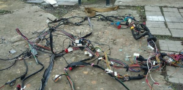
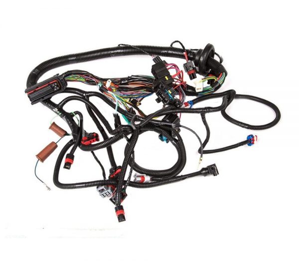
Bundles (harnesses) of wires
In order to facilitate installation work, all wires in the car are bundled. This is done either with adhesive tape, or by placing the conductors in plastic tubes. The beams are connected to each other by means of multi-pin connectors (blocks) made of polyamide plastic. In order to be able to pull the wiring through the elements of the body, technological holes are provided in it, which are usually closed with rubber plugs that protect the wires from chafing against the edges.
In the "seven" there are only five bundles of wiring, three of which are in the engine compartment, and the other two are in the cabin:
- right harness (stretches along the mudguard on the right);
- left harness (stretched along the engine shield and engine compartment mudguard on the left side);
- battery harness (comes from the battery);
- a bundle of the dashboard (located under the dashboard, and goes to the headlight switches, turns, instrument panel, interior lighting elements);
- rear harness (stretches from the mounting block to the aft lighting fixtures, glass heater, fuel level sensor).
 VAZ 2107 has only five wiring harnesses
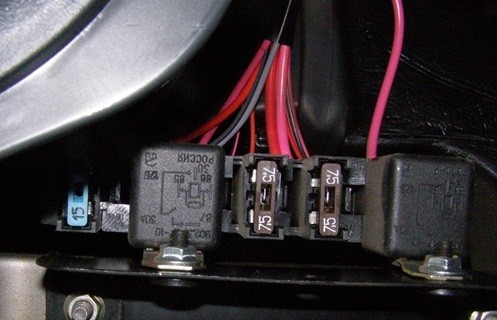
Mounting block
All wiring harnesses of the "seven" converge to the mounting block, which is installed in the right rear of the engine compartment. It contains the fuses and relays of the vehicle's on-board network. The mounting blocks of the carburetor and injection VAZ 2107 almost do not differ structurally, however, in the "sevens" with distributed injection there is an additional relay and fuse box, which is located in the cabin.
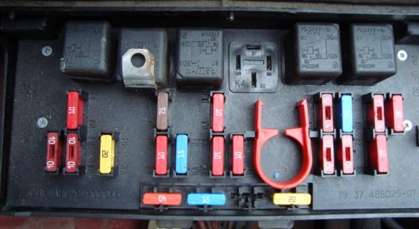
In addition, there are machines equipped with old-style blocks designed to use cylindrical fuses.
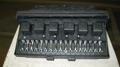
Consider what kind of protection elements ensure the safe operation of the VAZ 2107 on-board network.
Table: VAZ 2107 fuses and circuits protected by them
| Designation of the element on the diagram | Rated current (in blocks of the old sample / new sample), A | Protected electrical circuit |
| F-1 | 8/10 | Heating unit fan motor, rear window defroster relay |
| F-2 | 8/10 | Wiper motor, headlight bulbs, windshield washer motor |
| F-3 | Not used | |
| F-4 | ||
| F-5 | 16/20 | Rear window heating element |
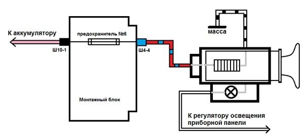
| F-6 | 8/10 | Clock, cigarette lighter, radio |
| F-7 | 16/20 | Signal, main radiator fan |
| F-8 | 8/10 | Lamps "turn signals" when the alarm is turned on |
| F-9 | 8/10 | Generator circuit |
| F-10 | 8/10 | Signal lamps on the instrument panel, the devices themselves, the “turn signal” lamps in the turn on mode |
| F-11 | 8/10 | Interior lamp, brake lights |
| F-12, F-13 | 8/10 | High beam lamps (right and left) |
| F-14, F-15 | 8/10 | Dimensions (right side, left side) |
| F-16, F-17 | 8/10 | Low beam lamps (right side, left side) |
Table: VAZ 2107 relay and their circuits
| Designation of the element on the diagram | Inclusion circuit |
| R-1 | Rear window heater |
| R-2 | Windshield washer and wiper motors |
| R-3 | Signal |
| R-4 | Radiator fan motor |
| R-5 | High beam |
| R-6 | Low beam |
The turn relay in the "seven" is not installed in the mounting block, but behind the instrument panel!
As already mentioned, in the injector "sevens" there is an additional relay and fuse box. It is located under the glove box.
It contains power elements that ensure the operation of the main electrical circuits of the car.
Table: fuses and relays of the additional mounting block VAZ 2107 injector
| Name and designation of the element on the diagram | Purpose |
| F-1 (7,5 A) | Main relay fuse |
| F-2 (7,5 A) | ECU fuse |
| F-3 (15 A) | Fuel pump fuse |
| R-1 | Main (main) relay |
| R-2 | Fuel pump relay |
| R-3 | Radiator fan relay |
More about the VAZ 2107 fuel pump: https://bumper.guru/klassicheskie-modeli-vaz/toplivnaya-sistema/benzonasos-vaz-2107-inzhektor.html
On-board network systems VAZ 2107 and the principle of their operation
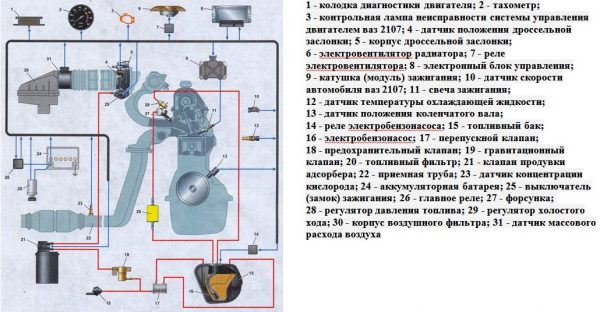
Considering that the "sevens" were produced both with carburetor engines and with injection engines, their electrical circuits are different.
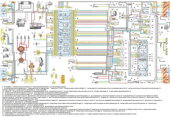
The difference between them lies in the fact that the latter have an on-board network supplemented with an electronic control unit, an electric fuel pump, injectors, as well as sensors for the engine control system.
Regardless of this, all electrical equipment of the "seven" can be divided into several systems:
- power supply of the car;
- start-up of the power plant;
- ignition;
- outdoor, indoor lighting and light signaling;
- sound alarm;
- additional equipment;
- engine management (in injection modifications).
Consider what these systems consist of and how they function.
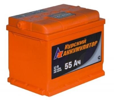
Power supply system
The VAZ 2107 power supply system includes only three elements: a battery, a generator and a voltage regulator. The battery is used to provide electricity to the vehicle's on-board network when the engine is off, as well as to start the power plant by supplying power to the starter. The "sevens" use lead-acid starter batteries of the 6ST-55 type with a voltage of 12 V and a capacity of 55 Ah. Their characteristics are quite enough to ensure the start of both carburetor and injection engines.
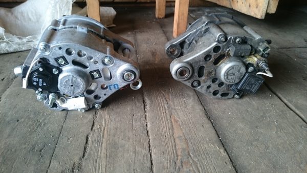
The car generator is designed to provide electric current to the on-board network of the car, as well as to charge the battery when the power unit is running. "Sevens" until 1988 were equipped with generators of the G-222 type. Later, the VAZ 2107 began to be equipped with current sources of the 37.3701 type, which managed to successfully prove themselves on the VAZ 2108. In fact, they have the same design, but differ in the characteristics of the windings.
Generator 37.3701 is a three-phase AC electromechanical device with electromagnetic excitation. Taking into account the fact that the on-board network of the "seven" is designed for direct current, a rectifier is installed in the generator, which is based on a six-diode bridge.
The generator is installed on the power plant of the machine. It is driven by a V-belt from the crankshaft pulley. The amount of voltage generated by the device depends on the number of revolutions of the crankshaft. In order for it not to go beyond the limits established for the on-board network (11,0–14,7 V), a microelectronic voltage regulator of the Ya112V type works in tandem with the generator. This is a non-separable and non-adjustable element that automatically and continuously smooths out voltage surges and drops, maintaining it at a level of 13,6-14,7 V.
The generator begins to generate current even when we turn the key in the ignition switch to position "II". At this moment, the ignition relay is turned on, and the voltage from the battery is supplied to the exciting winding of the rotor. In this case, an electromotive force is formed in the generator stator, which induces an alternating current. Passing through the rectifier, the alternating current is converted to direct current. In this form, it enters the voltage regulator, and from there to the on-board network.
Also check out the wiring diagram of the VAZ 21074: https://bumper.guru/klassicheskie-modeli-vaz/elektrooborudovanie/vaz-21074-inzhektor-shema-elektrooborudovaniya-neispravnosti.html
Video: how to find a generator malfunction

Power plant start system
The VAZ 2107 engine start system includes:
- Battery;
- starter with relay;
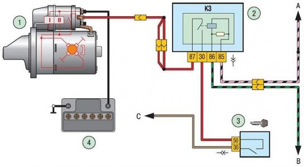
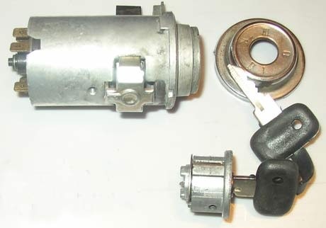
- ignition switch (lock).1 - starter; 2 - relay; 3 - ignition switch; 4 - battery
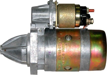
As a device for starting the power unit in the VAZ 2107, a four-brush DC electric starter of the ST-221 type was used. Its circuit is not protected by a fuse, but it provides two relays: auxiliary (power supply) and retractor, which ensures the coupling of the shaft of the device with the flywheel. The first relay (type 113.3747-10) is located on the motor shield of the machine. The solenoid relay is mounted directly on the starter housing.
The engine start is controlled by the ignition switch located on the steering block. It has four positions, by translating the key into which we are able to turn on the circuits of various electrical equipment:
- "0" - the position at which all electrical devices are turned off with the exception of the sound signal, cigarette lighter, interior ceiling lamp, sometimes the radio (depending on how it is connected);
- "III" - the lamps of the headlights of outdoor lighting, the windshield washer and the "wipers" are powered;
- "I" - power is supplied to the ignition system, to the dashboard, light signaling lamps and the heater fan;
- "II" - current is supplied to the starter relay, retractor and starter excitation windings.
Starting the engine is as follows. When the key is turned to the “II” position, the corresponding contacts of the ignition switch are closed, and the current flows to the outputs of the auxiliary relay, starting the electromagnet. When its contacts are also closed, power is supplied to the windings of the retractor. At the same time, voltage is supplied to the starter. When the solenoid relay is activated, the rotating shaft of the starting device engages with the flywheel crown and through it transmits torque to the crankshaft.
When we release the ignition key, it automatically returns from position "II" to position "I", and the current stops being supplied to the auxiliary relay. Thus, the starter circuit is opened, and it turns off.
Video: if the starter does not turn

Ignition system
The ignition system is designed for timely ignition of the combustible mixture in the combustion chambers of the power plant. Until 1989, inclusive, a contact-type ignition was installed on the VAZ 2107. Its design was:
- coil, which is a step-up transformer;
- distributor with contact breaker;
- high voltage wires;
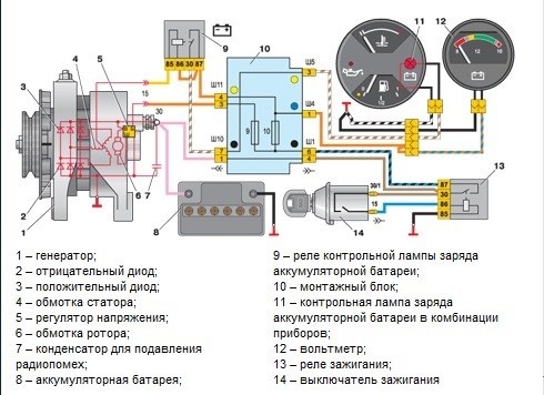
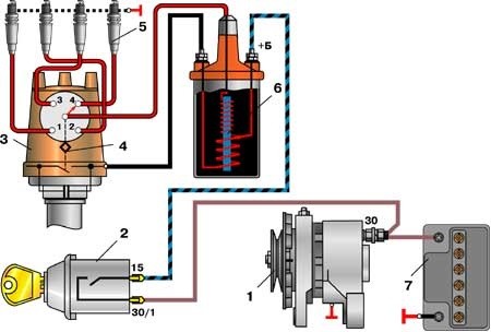
- candles.1 - generator; 2 - ignition lock; 3 - distributor; 4 - interrupter; 5 - candles; 6 - coil; 7 - battery
The ignition coil is used to increase the amount of voltage supplied from the battery. In the classical (contact) ignition system, a two-winding coil of type B-117A was used, and in a non-contact one - 27.3705. Structurally, they do not differ. The difference between them lies only in the characteristics of the windings.
Video: repair of the ignition system VAZ 2107 (part 1)

The distributor is necessary for interrupting the current and distributing voltage pulses across the candles. In the "sevens" distributors of the type 30.3706 and 30.3706-01 were installed.
By means of high-voltage wires, high-voltage current is transmitted from the contacts of the distributor cap to the candles. The main requirement for wires is the integrity of the conductive core and insulation.
Spark plugs form a spark at their electrodes. The quality and time of the fuel combustion process directly depend on its size and power. From the factory, VAZ 2107 engines were equipped with candles of type A -17 DV, A-17 DVR or FE-65PR with an interelectrode gap of 0,7–0,8 mm.
The contact ignition system worked as follows. When the ignition was turned on, the voltage from the battery went to the coil, where it increased several thousand times and followed the contacts of the breaker located in the ignition distributor housing. Due to the rotation of the eccentric on the distributor shaft, the contacts closed and opened, creating voltage pulses. In this form, the current entered the distributor slider, which "carried" it along the contacts of the cover. These contacts were connected to the center electrodes of the spark plugs via high voltage wires. This is how the voltage went from the battery to the candles.
After 1989, the "sevens" began to be equipped with a non-contact type ignition system. This was due to the fact that the breaker contacts constantly burned out and became unusable after five to eight thousand runs. In addition, drivers often had to adjust the gap between them, as it constantly went astray.
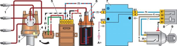
There was no distributor in the new ignition system. Instead, a Hall sensor and an electronic switch appeared in the circuit. The way the system works has changed. The sensor read the number of revolutions of the crankshaft and transmitted an electronic signal to the switch, which, in turn, generated a low voltage pulse and sent it to the coil. There, the voltage increased and was applied to the distributor cap, and from there, according to the old scheme, it went to the candles.
Video: repair of the ignition system VAZ 2107 (part 2)

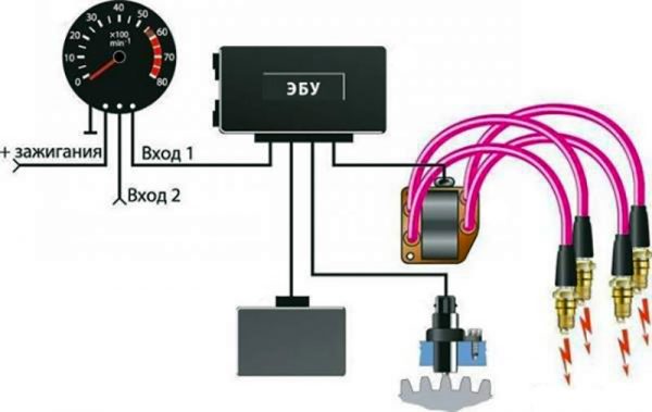
In the injection "sevens" everything is much more modern. Here, there are no mechanical components in the ignition system at all, and a special module plays the role of the ignition coil. The operation of the module is controlled by an electronic unit that receives information from several sensors and, based on it, generates an electrical impulse. Then he transfers it to the module, where the voltage of the pulse rises and is transmitted through high-voltage wires to the candles.
System of external, internal lighting and light signaling
The car lighting and signaling system is designed to illuminate the interior of the passenger compartment, the road surface in the front and rear of the car at night or in conditions of limited visibility, as well as to warn other road users about the direction of the maneuver by giving light signals. The system design includes:
- front headlights;
- repeaters of turns (side indicators);
- rear lights;
- salon ceiling.The lighting system includes front and rear lights, repeaters, interior ceiling
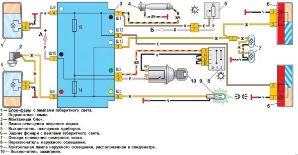
VAZ 2107 was equipped with two front headlights, each of which combined high and low beam headlights, side lights and direction indicators in its design. Far and near lighting in them is provided by one double-filament halogen lamp of the AG-60/55 type, the operation of which is controlled by a switch located on the steering column on the left. A type A12–21 lamp is installed in the direction indicator unit. It turns on when you move the same switch up or down. Dimensional light is provided by A12-4 type lamps. They light up when the outdoor light switch is pressed. The repeater also uses A12-4 lamps.
The rear lights of the "seven" are divided into four sections:
- direction indicator (lamp А12–21–3);
- side light (А12–4);
- fog light (A12-21-3);
- reversing lights (A12-21-3).
The rear fog lights come on when you press the button for turning them on, which is located on the center console of the car. The reversing lamps turn on automatically when reverse gear is engaged. A special “frog” switch installed at the rear of the gearbox is responsible for their work.
The interior of the car is illuminated with a special ceiling lamp located on the ceiling. Turning on its lamp occurs when the parking lights are turned on. In addition, its connection diagram includes door limit switches. Thus, the ceiling lights up when the side lights are on and at least one of the doors is open.
Sound alarm system
The sound alarm system is designed to give an audible signal to other road users. Its design is very simple, and consists of two electrical horns (one high tone, the other low), relay R-3, fuse F-7 and a power button. The sound alarm system is constantly connected to the on-board network, so it works even when the key is pulled out of the ignition lock. It is activated by pressing the button located on the steering wheel.
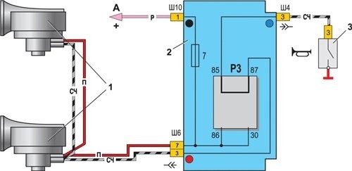
Signals like 906.3747–30 act as sound sources in the "sevens". Each of them has a tuning screw for adjusting the tone. The design of the signals is non-separable, therefore, if they fail, they must be replaced.
Video: VAZ 2107 sound signal repair

Additional electrical equipment VAZ 2107
The additional electrical equipment of the "seven" includes:
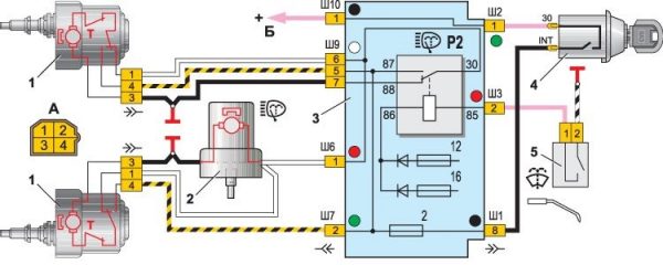
- windshield wiper gearmotors;
- windshield washer pump motor;
- cigarette lighter;
- heater fan motor;
- cooling radiator fan motor;
- clock.
The windscreen wiper motors actuate the trapezium, which in turn moves the "wipers" across the windshield of the car. They are installed in the rear of the engine compartment, immediately behind the motor shield of the machine. The VAZ 2107 uses gearmotors of the 2103–3730000 type. Power is supplied to the circuit when the right stalk is moved.
The washer motor drives the washer pump, which supplies water to the washer line. In the "sevens" the motor is included in the design of the pump built into the reservoir lid. Part number 2121-5208009. The washer motor is activated by pressing the right steering switch (towards you).
The cigarette lighter, first of all, serves not for the driver to be able to light a cigarette from him, but for connecting external electrical equipment: a compressor, navigator, video recorder, etc.
The cigarette lighter connection diagram consists of only two elements: the device itself and the F-6 fuse. Switching on is carried out by pressing the button located in its upper part.
The heater blower motor is used to force air into the vehicle interior. It is installed inside the heating block. The device catalog number is 2101–8101080. The operation of the electric motor is possible in two speed modes. The fan is turned on with a three-position button located on the dashboard.
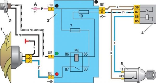
The radiator cooling fan motor is used to force airflow from the vehicle's main heat exchanger when the coolant temperature exceeds the allowable values. Its connection schemes for carburetor and injection "sevens" are different. In the first case, it turns on by a signal from a sensor installed in the radiator. When the coolant is heated to a certain temperature, its contacts close, and voltage begins to flow into the circuit. The circuit is protected by relay R-4 and fuse F-7.
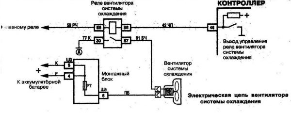
In injection VAZ 2107, the scheme is different. Here the sensor is not installed in the radiator, but in the cooling system pipe. Moreover, it does not close the fan contacts, but simply transmits data on the temperature of the refrigerant to the electronic control unit. The ECU uses this data to calculate most of the commands related to the operation of the engine, incl. and to turn on the radiator fan motor.
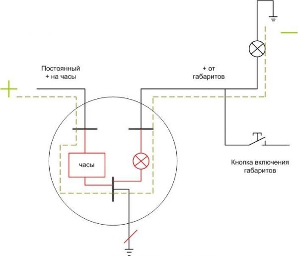
The clock is installed in the car on the dashboard. Their role is to show the time correctly. They have an electromechanical design and are powered by the machine's on-board network.
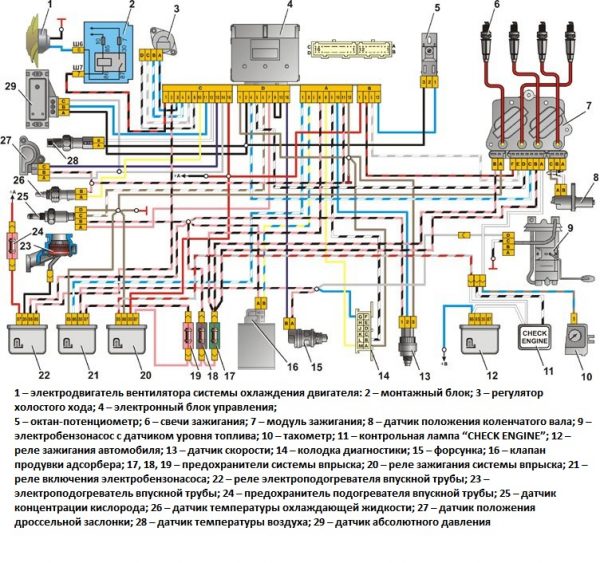
Engine management system
Only injection power units are equipped with a control system. Its main tasks are to collect information about the operating modes of various systems, mechanisms and engine components, process them, generate and send appropriate commands to control devices. The design of the system includes an electronic unit, nozzles and a number of sensors.
The ECU is a kind of computer in which a program is installed to control the operation of the engine. It has two types of memory: permanent and operational. The computer program and engine parameters are stored in the permanent memory. The ECU controls the operation of the power unit, checking the health of all components of the system. In the event of a breakdown, it puts the engine into emergency mode and gives a signal to the driver by turning on the “CHEK” lamp on the instrument panel. The RAM contains the current data received from the sensors.
Injectors are designed to supply gasoline to the intake manifold under pressure. They spray it and inject it into the receiver, where a combustible mixture is formed. At the heart of the design of each of the nozzles is an electromagnet that opens and closes the nozzle of the device. The electromagnet is controlled by the ECU. It sends electrical impulses at a certain frequency, due to which the electromagnet turns on and off.
The following sensors are included in the control system:
- Throttle position sensor. It determines the position of the damper relative to its axis. Structurally, the device is a variable-type resistor that changes resistance depending on the angle of rotation of the damper.
- Speed sensor. This element of the system is installed in the speedometer drive housing. A speedometer cable is connected to it, from which it receives information and transmits it to the electronic unit. The ECU uses its impulses to calculate the speed of the car.
- Coolant temperature sensor. As already mentioned, this device serves to determine the degree of heating of the refrigerant that circulates in the cooling system.
- crankshaft position sensor. It generates signals about the position of the shaft at a certain point in time. This data is necessary for the computer to synchronize its work with the cycles of the power plant. The device is installed in the camshaft drive cover.
- Oxygen concentration sensor. Serves to determine the amount of oxygen in the exhaust gases. Based on this information, the ECU calculates the proportions of fuel and air to form the optimal combustible mixture. It is installed in the intake just behind the exhaust manifold.
- Mass air flow sensor. This device is designed to calculate the volume of air entering the intake manifold. Such data is also needed by the ECU for the correct formation of the fuel-air mixture. The device is built into the air duct.The operation of all systems and mechanisms is controlled by the ECU
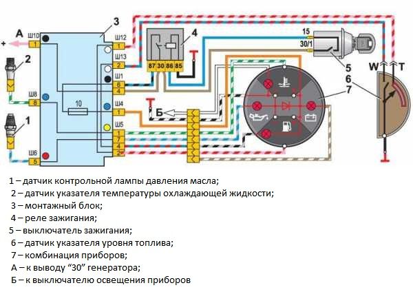
Information sensors
The VAZ 2107 information sensors include an emergency oil pressure sensor and a fuel gauge. These devices are not included in the engine management system, as it can work well without them.
The emergency oil pressure sensor is designed to determine the pressure in the lubrication system and promptly notify the driver of its decrease to critical levels. It is installed in the engine block and is connected to a signal lamp displayed on the instrument panel.
The fuel level sensor (FLS) is used to determine the amount of fuel in the tank, as well as to warn the driver that it is running out. The sensor is installed in the gas tank itself. It is a variable resistor, the slider of which is attached to the float. The fuel level sensor is connected to an indicator located on the instrument panel and a warning light located there.
The main malfunctions of electrical equipment VAZ 2107
As for breakdowns of electrical equipment in the VAZ 2107, there can be as many as you like, especially when it comes to an injection car. The table below shows the main malfunctions associated with electrical appliances of the "seven" and their symptoms.
Table: malfunctions of electrical equipment VAZ 2107
| Evidence | Malfunctions |
| Starter does not turn on | The battery is discharged. There is no contact with the "mass". Faulty traction relay. Break in the windings of the rotor or stator. The ignition switch is defective. |
| The starter turns but the engine does not start | The fuel pump relay (injector) has failed. Fuel pump fuse burned out. A break in the wiring in the area of the ignition switch-coil-distributor (carburetor). Faulty ignition coil (carburetor). |
| Engine starts but runs erratically at idle | Malfunction of one of the sensors of the engine management system (injector). Breakdown of high voltage wires. Incorrect gap between the contacts of the breaker, wear of the contacts in the distributor cap (carburetor). Faulty spark plugs. |
| One of the external or internal lighting devices does not work | Faulty relay, fuse, switch, broken wiring, lamp failure. |
| The radiator fan does not turn on | The sensor is out of order, the relay is faulty, the wiring is broken, the electric drive is faulty. |
| Cigarette lighter not working | The fuse has blown, the cigarette lighter coil has blown, there is no contact with the ground. |
| The battery drains quickly, the battery warning light is on | Malfunction of the generator, rectifier or voltage regulator |
Video: troubleshooting the VAZ 2107 on-board network

As you can see, even such a seemingly simple car as the VAZ 2107 has a rather complex on-board network, but you can deal with it if you wish.

