P064D Internal Control Module O2 Sensor Processor Performance Bank 1
Content
- P064D Internal Control Module O2 Sensor Processor Performance Bank 1
- OBD-II DTC Datasheet
- What does this mean?
- What is the severity of this DTC?
- What are some of the symptoms of the code?
- What are some of the common causes for the code?
- What are some steps to troubleshoot the P064D?
- Related DTC discussions
- Need more help with your P064D code?
P064D Internal Control Module O2 Sensor Processor Performance Bank 1
OBD-II DTC Datasheet
Internal Control Module O2 Sensor Processor Performance Bank 1
What does this mean?
This is a generic powertrain diagnostic trouble code (DTC) and is commonly applied to OBD-II vehicles. This may include, but is not limited to, Ford, Mazda, Smart, Land Rover, Dodge, Ram, etc. Despite the general nature, the exact repair steps may vary depending on the model year, make, model and transmission configuration.
When the P064D code persists, it means the powertrain control module (PCM) has detected an internal processor performance error with the heated oxygen sensor (HO2S) circuit for the first row of engines. Other controllers may also detect an internal PCM performance error (with HO2S for bank one)) and cause P064D to be stored.
Bank 1 denotes the engine group that contains cylinder number one.
The HO2S consists of a zirconia sensing element and a tiny sample chamber enclosed in a vented steel housing. The sensing element connects to the wires in the HO2S harness with small platinum electrodes. The oxygen sensor (HO2S) harness is connected to the engine control harness, which provides the PCM with data related to the percentage of oxygen in the engine exhaust compared to the oxygen in the ambient air.
The upstream HO2S sensor is located in the exhaust pipe (between the exhaust manifold and the catalytic converter). The most common method of achieving this is by inserting the sensor directly into a threaded bushing welded to the exhaust pipe. The threaded bushing is placed in the downpipe in the most convenient position and at the most convenient angle for access and optimum sensor performance. Removal and installation of threaded oxygen sensors will require specially designed wrenches or sockets, depending on the application of the vehicle. The HO2S can also be secured with threaded studs (and nuts) welded to the exhaust pipe.
Exhaust gases are pushed through the exhaust manifold into the downpipe where they pass through the upstream HO2S. Exhaust gases pass through specially designed vents in the steel housing of the oxygen sensor (HO2S) and through the sensing element. Ambient air is drawn into a small sample chamber in the center of the sensor through the wire holes. In this chamber, the air heats up, causing the ions to produce (energy) voltage. Differences between the concentration of oxygen molecules in the exhaust and the ambient air (drawn into the HO2S) cause fluctuations in the concentration of oxygen ions (inside the sensor). These vibrations cause the oxygen ions (inside the HO2S) to bounce (quickly and intermittently) from one platinum layer to the next. When pulsating oxygen ions move between the platinum layers, it causes voltage changes. These voltage changes are recognized by the PCM as changes in the oxygen concentration in the exhaust gas and reflect whether the engine is running lean (too little fuel) or rich (too much fuel). When more oxygen is present in the exhaust (lean state), the voltage output from the HO2S becomes lower. When less oxygen is present in the exhaust (rich state), the voltage output is higher. This data is used by the PCM, among other things, to calculate fuel strategy and ignition timing.
The input HO2S typically ranges from 100 to 900 millivolts (1 to 9 volts) when the engine is idling and the PCM is in closed loop mode. In closed-loop operation, the PCM takes input from the upstream HO2S to regulate the fuel injector pulse width and (ultimately) fuel delivery. When the engine enters open loop mode (cold start and wide open throttle conditions), the fuel strategy is pre-programmed.
The internal control module monitoring processors are responsible for the various controller self-testing functions and the overall accountability of the internal control module. The HO2S input and output signals are self-tested and monitored continuously by the PCM and other relevant controllers. The transmission control module (TCM), traction control module (TCSM), and other controllers also communicate with the HO2S.
Each time the ignition is turned on and the PCM is energized, the HO2S self-test is initiated. In addition to performing a self test on the internal controller, the Controller Area Network (CAN) also compares the signals from each individual module to ensure that each controller is working as expected. These tests are performed at the same time.
If the PCM detects an internal mismatch in HO2S functionality, a code P064D will be stored and a malfunction indicator lamp (MIL) may illuminate. In addition, if the PCM detects a problem between any of the on-board controllers that indicates an internal HO2S error, a P064D code will be stored and a malfunction indicator lamp (MIL) may illuminate. It may take several failure cycles to illuminate the MIL, depending on the perceived severity of the malfunction.
Photo of the PKM with the cover removed: 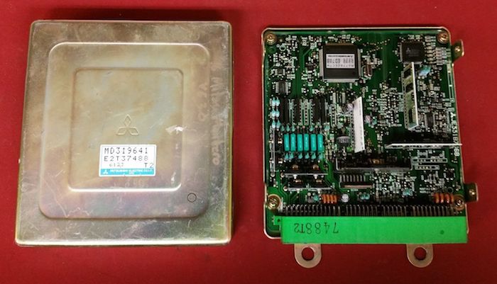
What is the severity of this DTC?
Internal control module processor codes are to be classified as Severe. A stored P064D code can result in a variety of handling problems, including reduced fuel efficiency.
What are some of the symptoms of the code?
Symptoms of a P064D trouble code may include:
- Reduced fuel efficiency
- General lack of engine power
- Various symptoms of engine drivability
- Other Stored Diagnostic Trouble Codes
What are some of the common causes for the code?
Causes of this P064D DTC may include:
- Faulty controller or programming error
- Bad HO2S
- Rich or Lean Exhaust Conditions
- Burnt, frayed, broken, or disconnected wiring and / or connectors
- Engine exhaust leaks
- Faulty controller power relay or blown fuse
- Open or short circuit in the circuit or connectors in the CAN harness
- Insufficient grounding of the control module
What are some steps to troubleshoot the P064D?
Even for the most experienced and well-equipped professional technician, diagnosing the P064D code can be challenging. There is also the problem of reprogramming. Without the necessary reprogramming equipment, it will be impossible to replace the faulty controller and carry out a successful repair.
If there are ECM / PCM power supply codes, they obviously need to be corrected before attempting to diagnose the P064D.
There are some preliminary tests that can be performed before declaring a controller as faulty. You will need a diagnostic scanner, a digital volt-ohmmeter (DVOM) and a source of reliable information about the vehicle.
Connect the scanner to the vehicle diagnostic port and get all stored codes and freeze frame data. You will want to write this information down just in case the code turns out to be intermittent. After recording all relevant information, clear the codes and test drive the vehicle until the code is cleared or the PCM enters standby mode. If the PCM enters ready mode, the code is intermittent and harder to diagnose. The condition that caused the P064D to be stored may even get worse before a diagnosis can be made. If the code is reset, continue with this short list of pre-tests.
When trying to diagnose a P064D, information can be your best tool. Search your vehicle information source for technical service bulletins (TSBs) that match the stored code, vehicle (year, make, model, and engine) and symptoms displayed. If you find the right TSB, it can provide diagnostic information that will help you to a great extent.
Use your vehicle information source to obtain connector views, connector pinouts, component locators, wiring diagrams, and diagnostic block diagrams relevant to the code and vehicle in question.
Use the DVOM to test the fuses and relays of the controller power supply. Check and replace blown fuses if necessary. Fuses should be checked with a loaded circuit.
If all fuses and relays are working properly, a visual inspection of the wiring and harnesses associated with the controller should be performed. You will also want to check the chassis and motor ground connections. Use your vehicle information source to obtain grounding locations for associated circuits. Use DVOM to check ground integrity.
Visually inspect the system controllers for damage caused by water, heat, or collision. Any controller damaged, especially by water, is considered defective.
If the power and ground circuits of the controller are intact, suspect a faulty controller or a controller programming error. Replacing the controller will require reprogramming. In some cases, you can purchase reprogrammed controllers from the aftermarket. Other vehicles / controllers will require onboard reprogramming, which can only be done through a dealership or other qualified source.
HO2S Testing
Make sure the engine is running efficiently before attempting to diagnose the oxygen sensor (HO2S). Misfire codes, throttle position sensor codes, manifold air pressure codes, and MAF sensor codes must be reviewed before attempting to diagnose any HO2S or lean / rich exhaust codes.
Some automakers use a fused circuit to supply voltage to the HO2S. Check these fuses with DVOM.
If all fuses are OK, locate the HO2S for the first row of engines. The vehicle will need to be lifted with a suitable jack or jacked up and secured to safety stands. Once you have access to the sensor in question, disconnect the harness connector and place the key in the ON position. You are looking for the battery voltage at the HO2S connector. Use the circuit diagram to determine which circuit is used to supply the battery voltage. Also check that the system is grounded at this time.
If HO2S voltage and ground are present, reconnect the HO2S. Start the engine and test drive the vehicle. After a test drive, let the engine idle (in neutral or parked). Use the scanner to monitor the HO2S input data. Narrow down the data stream to include only the relevant data and you will get a faster data response. Assuming the engine is running efficiently, the upstream HO2S should switch regularly from rich to lean (and vice versa) with the PCM in closed loop.
- Unlike most other codes, P064D is likely caused by a faulty controller or a controller programming error.
- Check the system ground for continuity by connecting the negative test lead of the DVOM to ground and the positive test lead to the battery voltage.
Related DTC discussions
- There are currently no related topics in our forums. Post a new topic on the forum now.
Need more help with your P064D code?
If you still need help regarding DTC P064D, post a question in the comments below this article.
NOTE. This information is provided for informational purposes only. It is not intended to be used as a repair recommendation and we are not responsible for any action you take on any vehicle. All information on this site is protected by copyright.