AVT5540 B - a small RDS radio for everyone
Several interesting radio receivers have been published in the pages of Practical Electronics. Thanks to the use of modern components, many design problems, such as those associated with setting up RF circuits, have been avoided. Unfortunately, they created other problems - delivery and assembly.
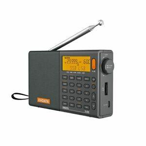
Photo 1. Appearance of the module with the RDA5807 chip
The module with the RDA5807 chip serves as a radio tuner. His plaque, shown on Photo 1dimensions 11 × 11 × 2 mm. It contains a radio chip, a quartz resonator and several passive components. The module is very easy to install, and its price is a pleasant surprise.
Na picture 2 shows the pin assignment of the module. In addition to applying a voltage of about 3 V, only a clock signal and an antenna connection are required. Stereo audio output is available, and RDS information, system status, and system configuration are read through the serial interface.
building
Figure 2. Internal diagram of the RDA5807 system
The circuit diagram of the radio receiver is shown in picture 3. Its structure can be divided into several blocks: power supply (IC1, IC2), radio (IC6, IC7), audio power amplifier (IC3) and control and user interface (IC4, IC5, SW1, SW2).
The power supply provides two stabilized voltages: +5 V to power the audio power amplifier and display, and +3,3 V to power the radio module and control microcontroller. The RDA5807 has a built-in low power audio amplifier, allowing you to drive, for example, headphones directly.
In order not to burden the output of such a thin circuit and to obtain more power, an additional audio power amplifier was used in the presented device. This is a typical TDA2822 application that achieves several watt output power.
The signal output is available on three connectors: CON4 (a popular minijack connector that allows you to connect, for example, headphones), CON2 and CON3 (allow you to connect speakers to the radio). Plugging in headphones disables the signal from the speakers.
Figure 3. Schematic diagram of the radio with RDS
installation
The assembly diagram of the radio receiver is shown in picture 4. Installation is carried out in accordance with the general rules. There is a place on the printed circuit board for mounting the finished radio module, but it also provides for the possibility of assembling individual elements that make up the module, i.e. RDA system, quartz resonator and two capacitors. Therefore, there are elements IC6 and IC7 on the circuit and on the board - when assembling the radio, choose one of the options that is more convenient and fits your components. The display and sensors must be installed on the solder side. Useful for assembly photo 5, showing the assembled radio board.
Figure 4. Scheme of installation of the radio with RDS
After assembly, the radio requires only adjustment of the display contrast using potentiometer R1. After that, he is ready to go.
Photo 5. Assembled radio board
Figure 6. Information shown on the display
service
Basic information is shown on the display. The bar displayed on the left shows the power level of the received radio signal. The central part of the display contains information about the currently set radio frequency. On the right - also in the form of a strip - the level of the sound signal is displayed (6).
After a few seconds of inactivity – if RDS reception is possible – the received frequency indication is “shadowed” by the basic RDS information and the extended RDS information is shown on the bottom line of the display. The basic information consists of only eight characters. Usually we see the name of the station there, alternating with the name of the current program or artist. The extended information can contain up to 64 characters. Its text scrolls along the bottom line of the display to show the full message.
The radio uses two pulse generators. The one on the left lets you set the received frequency, and the one on the right lets you adjust the volume. In addition, pressing the left button of the pulse generator allows you to store the current frequency in one of the eight dedicated memory locations. After selecting the program number, confirm the operation by pressing the encoder (7).
Figure 7. Memorizing the set frequency
In addition, the unit memorizes the last stored program and the set volume, and every time the power is turned on, it starts the program at this volume. Pressing the right pulse generator switches reception to the next stored program.
действие
The RDA5807 chip communicates with the microcontroller via the I serial interface.2C. Its operation is controlled by sixteen 16-bit registers, but not all bits and registers are used. Registers with addresses from 0x02 to 0x07 are mainly used for writing. At the beginning of the transmission I2C with the write function, register address 0x02 is automatically saved first.
Registers with addresses from 0x0A to 0x0F contain read-only information. Start of transmission2C to read state or contents of registers, RDS automatically starts reading from register address 0x0A.
Address I2According to the documentation, the C of the RDA system has 0x20 (0x21 for the read function), however, functions containing the address 0x22 were found in the sample programs for this module. It turned out that one specific register of the microcircuit can be written to this address, and not the entire group, starting from the register address 0x02. This information was missing from the documentation.
The following listings show the more important parts of a C++ program. Listing 1 contains definitions of important registers and bits - a more detailed description of them is available in the system documentation. On the listing 2 shows the procedure for initializing the integrated circuit of the RDA radio receiver. On the listing 3 represents the procedure for tuning the radio system to receive a given frequency. The procedure uses the write functions of a single register.
Acquiring RDS data requires continuous reading of the RDA registers containing the relevant information. The program contained in the memory of the microcontroller performs this action approximately every 0,2 seconds. There is a function for this. RDS data structures have already been described in the EP, for example during the AVT5401 project (EP 6/2013), so I encourage those interested in expanding their knowledge to read the article available for free in the archives of Practical Electronics (). At the end of this description, it is worth devoting a few sentences to the solutions used in the presented radio.
The RDS data received from the module is divided into four registers RDSA… RDSD (located in registers with addresses from 0x0C to 0x0F). The RDSB register contains information about the data group. Relevant groups are 0x0A containing RDS body text (eight characters) and 0x2A containing extended text (64 characters). Of course, the text is not in one group, but in many subsequent groups with the same number. Each of them contains information about the position of this part of the text, so you can complete the message as a whole.
Data filtering turned out to be a big problem in order to collect the correct message without “bushes”. The device uses a double buffered RDS message solution. The received message fragment is compared with its previous version, placed in the first buffer - the working one, in the same position. If the comparison is positive, the message is stored in the second buffer - the result. The method requires a lot of memory, but is very efficient.