AVT5598 – 12V Solar Charger
Photovoltaic modules are becoming cheaper and therefore becoming more popular. They can be successfully used to charge batteries, for example, in a country house or an electronic weather station. The described device is a charge controller adapted to work with an input voltage that varies over a very wide range. It can be useful on the site, in a camp site or camp site.
1. Schematic diagram of the solar charger
The system is used to charge a lead-acid battery (for example, gel) in buffer mode, i.e. after reaching the set voltage, the charging current begins to fall. As a result, the battery is always in standby mode. The supply voltage of the charger can vary within 4 ... 25 V.
The ability to use both strong and weak sunlight significantly increases the charging time per day. The charging current is highly dependent on the input voltage, but this solution has advantages over simply limiting the excess voltage from the solar module.
The charger circuit is shown in fig. 1. The DC power source is a SEPIC topology converter based on the cheap and well-known MC34063A system. It works in the typical role of a key. If the voltage supplied to the comparator (pin 5) is too low, the built-in transistor switch starts to work with a constant filling and frequency. Operation stops if this voltage exceeds the reference voltage (typically 1,25 V).
SEPIC topology converters, capable of both raising and lowering the output voltage, much more often use controllers that can change the padding of the keying signal. Using the MC34063A in this role is an infrequent solution, but - as shown by prototype testing - sufficient for this application. Another criterion was the price, which in the case of the MC34063A is significantly lower than that of PWM controllers.
Two capacitors C1 and C2 connected in parallel are used to reduce the internal resistance of a power supply such as a photovoltaic module. Parallel connection reduces the resulting parasitic parameters such as resistance and inductance. Resistor R1 is used to limit the current of this process to about 0,44A. Higher current can cause the integrated circuit to overheat. Capacitor C3 sets the operating frequency to about 80 kHz.
Inductors L1 and L2 and the resulting capacitance of capacitors C4-C6 are selected so that the converter can operate in a very wide voltage range. Parallel connection of capacitors was supposed to reduce the resulting ESR and ESL.
Diode LED1 is used to test the functionality of the controller. If so, then the variable component of the voltage is deposited on the coil L2, which can be observed by the glow of this diode. It turns on by pressing the S1 button so that it does not glow senselessly all the time. Resistor R3 limits its current to about 2 mA, and D1 protects the LED diode from breakdown caused by excessive turn-off voltage. Resistor R4 is added for better converter stability at low current consumption and low voltage. It absorbs some of the energy that the L2 coil gives to the load. It affects the efficiency, but is small - the effective value of the current flowing through it is only a few milliamps.
Capacitors C8 and C9 smooth out the ripple current supplied through diode D2. Resistive divider R5-R7 sets the output voltage to approximately 13,5V, which is the correct voltage at the 12V gel battery terminals during buffer operation. This voltage should vary slightly with temperature, but this fact has been omitted to keep the system simple. This resistor divider loads the connected battery all the time, so it should have the highest possible resistance.
Capacitor C7 reduces the voltage ripple seen by the comparator and slows down the response of the feedback loop. Without it, when the battery is disconnected, the output voltage may exceed the safe value for electrolytic capacitors, i.e. escape. The addition of this capacitor causes the system to stop switching the key from time to time.
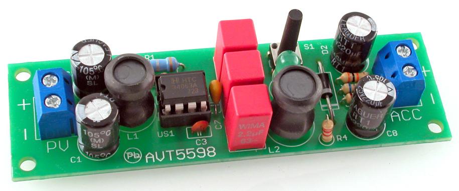
The charger is mounted on a single-sided printed circuit board with dimensions of 89 × 27 mm, the assembly diagram of which is shown in Fig. picture 2. All elements are in through-hole housings, which is a great help even for people who do not have much experience with a soldering iron. I suggest not using an IC socket because that will increase the resistance of the connections to the switch transistor.
2. Solar charger installation diagram
A correctly assembled device is immediately ready for operation and does not require any commissioning. As part of the control, you can apply a constant voltage to its input and regulate it in a given range of 4 ... 20 V, observing the readings of a voltmeter connected to the output. It should change sawtooth in the range of approximately 18 ... 13,5 V. The first value is related to the charging of the capacitors and is not critical, but at 13,5 V the converter should work again.
The charging current depends on the current value of the input voltage, since the input current is limited to approximately 0,44 A. Measurements have shown that the battery charging current varies from approximately 50 mA (4 V) to approximately 0,6 A.A at a voltage of 20 V. You can reduce this value by increasing the resistance R1, which is sometimes advisable for small capacity batteries (2 Ah).
The charger is adapted to work with a photovoltaic module with a nominal voltage of 12 V. Voltages up to 20 ... 22 V can be present at its outputs with low current consumption, therefore, capacitors adapted to the voltage of 25 V are installed at the input of the converter. The losses are so high that the battery is hardly charged.
To take full advantage of the charger, connect a module with a power of 10 W or more. With less power, the battery will also charge, but more slowly.
Component List:
Resistors:
R1: 0,68 Ohm / 1 W.
R2: 180 Ohm / 0,25 W.
R3: 6,8 kΩ / 0,25 W
R4: 2,2 kΩ / 0,25 W
R5: 68 kΩ / 0,25 W
R6: 30 kΩ / 0,25 W
R7: 10 kΩ / 0,25 W
Capacitors:
C1, C2, C8, C9: 220 μF / 25 V
C3: 330 pF (ceramic)
C4…C6: 2,2 μF/50 V (MKT R = 5 mm)
C7: 1µF/50V (monolith.)
Semiconductors:
D1: 1H4148
D2: 1H5819
LED1: 5mm LED, e.g. green
US1:MC34063A(DIP8)
others:
J1, J2: ARK2/5mm connector
L1, L2: Choke 220uH (Vertical)
S1: micro switch 6×6/13mm