AVT795 - running light
More and more people would like to practically be interested in electronics and build various circuits, but they think that it is very difficult. Anyone with a strong will can successfully take up electronics as an attractive, extremely passionate hobby. For those who want to start their electronic adventure right away but don't know how, AVT offers a series of simple projects with the three digit designation AVT7xx. Another one from this series is the “running light” AVT795.
The effect of a light chain producing a series of flashes is reminiscent of a meteorite fall. The presented electronic system can be used, among other things, as entertainment for toys or a showcase, and due to the use of several such systems with different LED colors, even for a small house party. Getting to know the principle of operation will allow you to use the effect of traveling light in an even more creative way.
How does it work?
Schematic diagram of the dimmer is shown in Figure 1. The basic element is counter U1. This counter is controlled by two generators. The cycle time of the generator built on the U2B amplifier is about 1 s, while the duration of the high state at the output of this generator is about ten times less due to the presence of D1 and R5.
1. Electrical diagram of the system
For the entire time of the high state at the input RES - output 15, the counter is reset, i.e. a high state is present at output Q0, to which no LEDs are connected. At the end of the reset pulse, the counter starts counting pulses from the generator built on the U2A amplifier, applied to the CLK input of the meter - feet 14. In the rhythm of the generator built on the U2A amplifier, the diodes D3 ... D8 will light up. light up in sequence. When a high state appears at the Q9 output connected to the ENA input - pin 13, the counter will stop counting pulses - all LEDs will remain off until the counter is reset by the generator built on the U2B amplifier, it will start a new cycle and produce a series of flashes. Similarly, the diode is off when a high state appears at the output of the oscillator built on the amplifier U2B and at the input RES of the cube U1. This will reset counter U1. Supply voltage range 6…15 V, average current consumption about 20 mA at 12 V.
Possibility of change
The layout can be changed in many ways as you see fit. First of all, in the basic system, you can change the repetition time of a series of flashes by changing the capacitance C1 (100 ... 1000 μF) and, possibly, R4 (4,7 kOhm ... ) and resistance R220 (2 kOhm ... 1 kOhm). Due to the lack of a current limiting resistor, LEDs are relatively bright.
The model system uses yellow LEDs. Nothing prevents you from changing their color and using several of these systems, which can be a great addition to the lighting of many residential buildings. With a supply voltage of 12 V, instead of one diode, you can safely connect two or even three diodes in series and thus build a light chain containing several LEDs.
Installation and adjustment
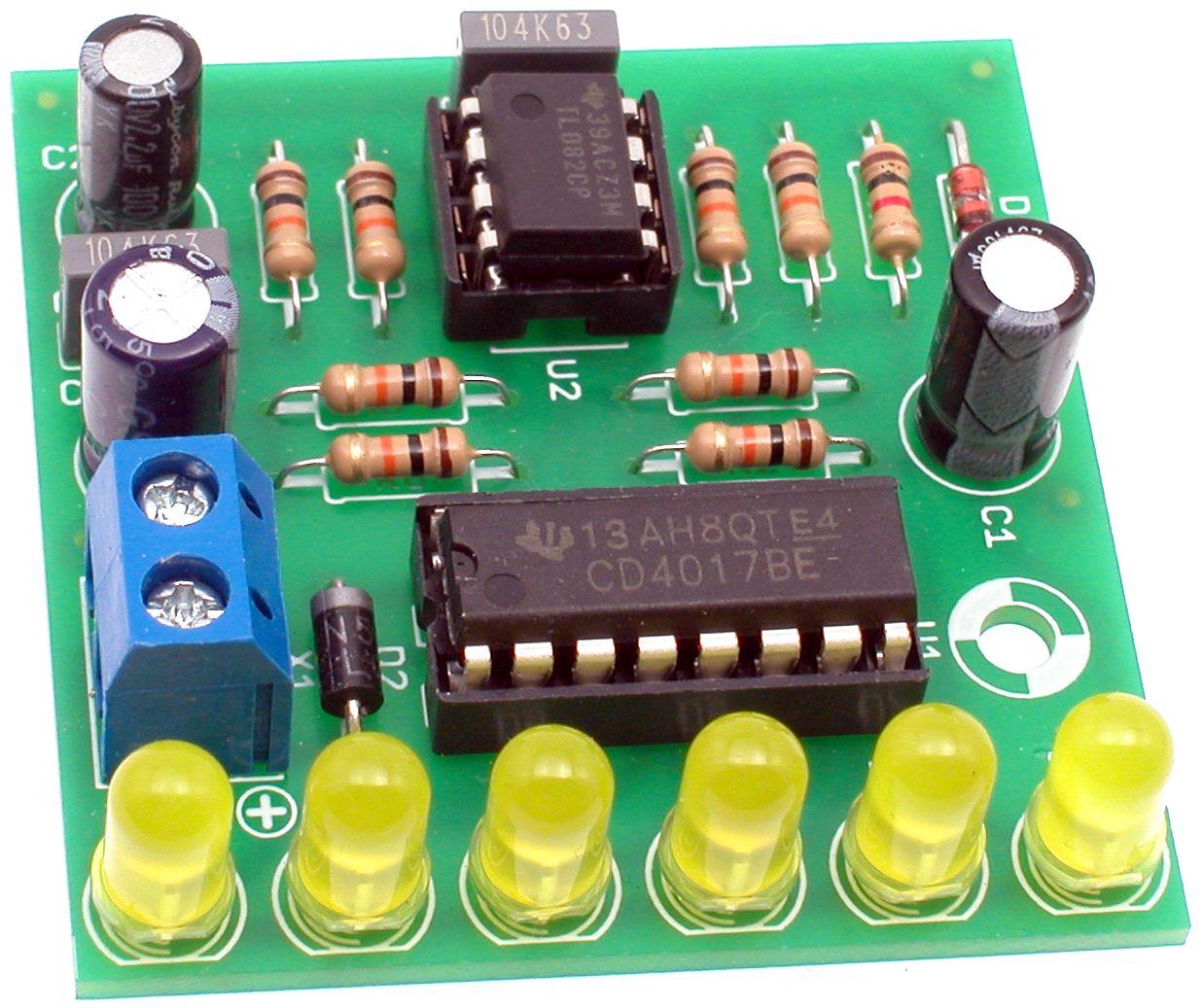
The title photo will be useful during installation work. Even less experienced designers will cope with the assembly of the system, and it is best to start this stage by soldering the elements to the printed circuit board, starting with the smallest and ending with the largest. The recommended assembly sequence is indicated in the parts list. In the process, pay special attention to the method of soldering pole elements: electrolytic capacitors, diodes and integrated circuits, the cutout in the case of which must match the pattern on the printed circuit board.
After checking the correct installation, you should connect a stabilized power supply, preferably with a voltage of 9 ... 12 V, or an alkaline 9-volt battery. Rysunek 2 shows how to properly connect the power supply to the circuit board and shows the sequence of turning on the LEDs. Correctly assembled from working elements, the system will immediately work properly and does not require any configuration or launch. The printed circuit board has a mounting hole and four solder points where you can solder cut pieces of silverware or cut off the ends of resistors after soldering. Thanks to them, the finished system can be easily attached or placed on the surface provided for this.
2. Correct connection of the power supply to the board and the order of turning on the LEDs.
All necessary parts for this project are included in the AVT795 B kit for PLN 16, available at: