RPM sensor
 The engine speed is determined by the controller based on the signal generated by the inductive crankshaft speed sensor.
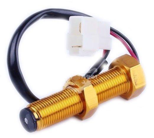
The sensor works with a gear ferromagnetic impulse wheel and can be placed on the crankshaft in 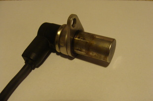 pulley or flywheel. Inside the sensor, the coil is wound around a mild steel core, one end of which is connected to a permanent magnet to form a magnetic circuit. The lines of force of the magnetic field penetrate the gear part of the impulse wheel, and the magnetic flux covering the coil winding depends on the relative position of the end face of the sensor and the teeth and the gaps between the teeth on the impulse wheel. As the teeth and throats alternately pass the sensor, the magnetic flux changes and induces a sinusoidal alternating output voltage in the coil winding. The voltage amplitude increases with increasing rotation speed. The inductive sensor allows you to measure the speed from 50 rpm.
With the help of an inductive sensor it is also possible to recognize a certain position of the crankshaft. To mark it, a reference point is used, made by removing two successive teeth on the impulse wheel. An increased interdental notch leads to the fact that an alternating voltage with an amplitude greater than the voltage amplitude induced by the remaining teeth and interdental notches of the impulse wheel is created in the winding of the sensor coil.
If there is only one crankshaft speed and position sensor in the control system, the absence of a signal makes it impossible to calculate the ignition timing or fuel dose. In this case, none of the replacement values programmed in the controller can be used.
In complex integrated injection-ignition systems, substitute signals are taken from the camshaft sensors in the absence of a signal from the speed and crankshaft position sensor. Engine control is degraded, but at least it can work in the so-called Safe Mode.