ABS sensors on Largus
Content
The anti-lock braking system provides more effective braking of the car by reducing the fluid pressure in the brakes at the time of their blocking. The fluid from the master brake cylinder enters the ABS unit, and from there it is supplied to the brake mechanisms.
The hydraulic block itself is fixed on the right side member, near the bulkhead, it consists of a modulator, a pump and a control unit.
The unit works depending on the readings of the wheel speed sensors.
When the vehicle is braked, the ABS unit detects the start of the wheel lock and opens the corresponding modulating solenoid valve to release the pressure of the working fluid in the channel.
The valve opens and closes several times per second to ensure that the ABS is activated by a slight jolt in the brake pedal when braking.
Removing the ABS unit
We install the car in an elevator or in a gazebo.
Disconnect the negative battery terminal.
We unscrew the three nuts securing the soundproofing to the front panel and the right wing and move the soundproofing to access the hydraulic group (flat screwdriver).
Disconnect plug-in block 7, fig. 1, from the front cable harness.
Disconnect the brake lines from the anti-lock brake hydraulic unit. We install plugs in the openings of the valve body and in the brake pipes (key for brake pipes, technological plugs).
We remove the front wiring harness 4 from support 2, the mass cable 10 from support 9 and the brake pipe 3 from support 6, fixing it on the valve body support (flat screwdriver).
Unscrew the screws 5 fastening the valve body support to the body and remove the hydraulic unit 1 complete with support 8 (replacement head 13, ratchet).
Unscrew the bolts securing the valve body to the mounting bracket and remove the valve body (replacement head for 10, ratchet).
Installation
Attention. When replacing the hydraulic unit, follow the ABS computer programming procedure.
To ensure the tightness of the connector of the valve body control unit, the terminal of the wire of the body mass of the valve body must be directed downwards.
Mount the hydraulic unit on the mounting bracket and secure with bolts. Screw tightening torque 8 Nm (0,8 kgf.m) (replaceable head for 10, ratchet, torque wrench).
Install the valve assembly with the bracket on the vehicle and secure with bolts. Screw tightening torque 22 Nm (2,2 kgf.m) (replaceable head for 13, ratchet, torque wrench).
Connect the plug of the front wiring harness to the hydroblock connector.
Install the wiring harness, ground wire, and brake hose to the hydraulic unit bracket mounting brackets (using a flathead screwdriver).
Remove the technological plugs from the openings of the valve body and brake pipes and connect the brake lines to the valve body. Tightening torque of fittings 14 Nm (1,4 kgf.m) (brake pipe wrench, torque wrench).
Connect the ground cable terminal to the battery (key 10).
Bleed the brake system.
Removal and installation of the sensor of speed of a forward wheel
Retirement
We remove the front wheel. We raise the car to a comfortable working height.
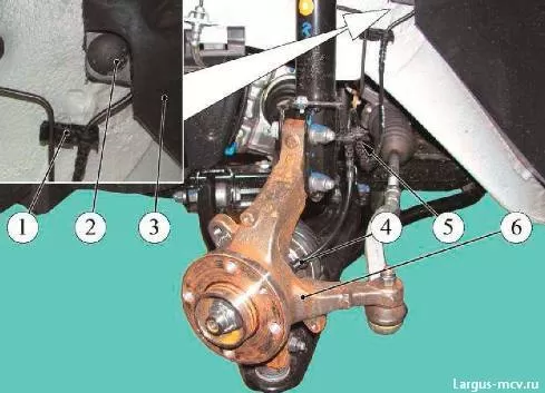
We remove the latch 2, Figure 2, from the protective cover of the front wheel arch in the area where the speed sensor wiring harness is located (flat screwdriver).
We take out the speed sensor harness from the grooves of the bracket 5 of the front suspension strut and the bracket 1 of the engine compartment fender liner.
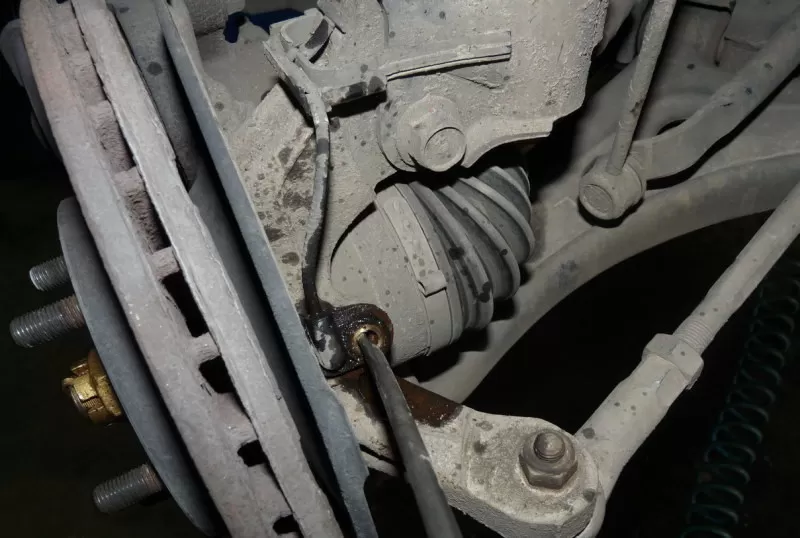
Foam plastic insulating material 1, fig. 3 (flathead screwdriver).
Remove the speed sensor 2 from the knuckle mounting hole by pressing the sensor retainer 3 with a screwdriver (flathead screwdriver).
Disconnect the speed sensor harness from the front harness and remove the sensor.
Installation
The insulating foam of the wheel speed sensor needs to be replaced.
Install the foam insulation in the speed sensor mounting socket on the steering knuckle.
Connect the speed sensor harness connector to the front harness.
Install the speed sensor into the mounting hole of the steering knuckle until the retainer is released.
Install the speed sensor harness into the grooves on the front suspension strut bracket and the engine compartment fender bracket.
Lock the front wheel arch protection with a lock.
Install the front wheel.
Removal and installation of the sensor of speed of rotation of a back wheel
Retirement
Remove the rear wheel.
Raise the vehicle to a comfortable working height.
Remove harness 2, fig. 4, the wires of the speed sensor from the slot of the bracket 1 and the latch Ç on the rear suspension arm.
Unscrew the screw 5 fastening the speed sensor to the rear brake shield and remove the sensor 6.
Unscrew two nuts 4, Figure 5, securing the cover of the rear wheel speed sensor shield harness (replacement head for 13, ratchet).
Unscrew the two screws securing the cover 2 and open the cover 3 (6) to access the speed sensor wiring harness block (flat screwdriver).
Remove the speed sensor harness from the housing brackets, disconnect the sensor harness connector 5 from the rear harness 7 and remove the sensor.
See also: bleeding your brakes
Connect the speed sensor harness connector to the rear ABS wiring harness and secure the sensor harness to the brackets on the cover.
Reinstall the speed sensor harness cover and secure it to the rear wheel arch with two clips and two nuts. The tightening torque of the nuts is 14 Nm (1,4 kgf.m) (replaceable head for 13, ratchet, torque wrench).
Installation
Install the speed sensor in the hole in the brake housing and secure it with the bolt. Bolt tightening torque 14 Nm (1,4 kgf.m).
Install the speed sensor harness into the bracket slot and into the rear suspension arm bracket.
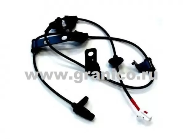
ABS sensor Lada Largus can be sold separately or assembled with a hub. Front and rear ABS sensors Lada Largus are different. Differences can be in the direction of installation - right and left can be different. Before buying an ABS sensor, it is necessary to conduct electrical diagnostics. It will determine if the ABS sensor or ABS unit is faulty.
In 20% of cases, after buying an ABS sensor Lada Largus, it turns out that the old sensor is working. I had to remove the sensor and clean it. It is better to install a new non-genuine ABS sensor than a used original one. If the ABS sensor is assembled with the hub, it will not be possible to buy and replace it separately.
The price of ABS sensor Lada Largus:
| Sensor options | Sensor price | Buy |
|---|---|---|
| ABS sensor front Lada Largus | from 1100 rubles. | |
| Rear ABS sensor Lada Largus | from 1300 rubles. | |
| ABS sensor front left Lada Largus | from 2500 rubles. | |
| Sensor ABS front right Lada Largus | from 2500 rubles. | |
| Sensor ABS rear left Lada Largus | from 2500 rubles. | |
| Sensor ABS rear right Lada Largus | from 2500 rubles. |
The cost of the ABS sensor depends on whether it is new or used, on the manufacturer, as well as on the availability in our warehouse or delivery time to our store.
If the ABS sensor is not available, we can try to assemble a connector from old sensors and solder it at our stations. The possibility of such work will be specified in each case during the actual inspection at the station.
Rating of manufacturers of ABS sensors
1. BOSCH (Germany)
2. Hella (Germany)
3. FAE (Spain)
4.ERA (Italy)
5. Patron (European Union)
When to buy an ABS sensor:
– the indicator ABS on the panel of devices lights up;
- mechanical damage to the ABS sensor;
- Broken ABS sensor wiring.
The working brake system is hydraulic, dual-circuit with diagonal separation of circuits. One of the circuits provides the brake mechanisms of the front left and rear right wheels, and the other - the front right and rear left wheels. In normal mode (when the system is running), both circuits work. In case of failure (depressurization) of one of the circuits, the other provides braking of the car, although with less efficiency.
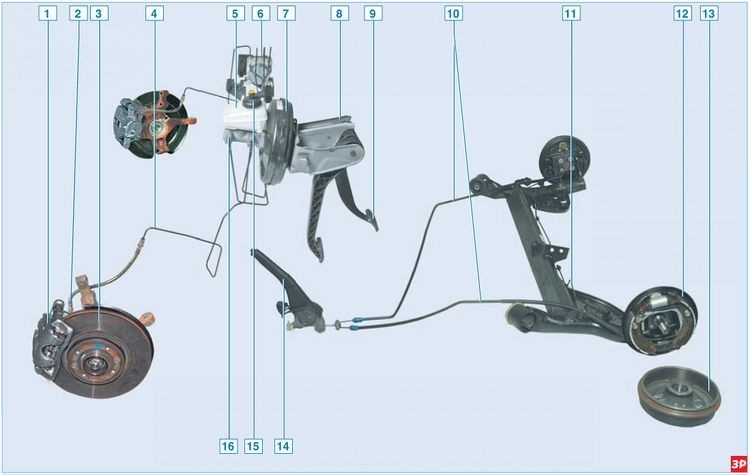
Elements of the brake system of a car with ABS
1 - floating bracket;
2 – a hose of the brake mechanism of a forward wheel;
3 – a disk of the brake mechanism of a forward wheel;
4 – a tube of the brake mechanism of a forward wheel;
5 – hydraulic drive tank;
6 - block ABS;
7 - vacuum brake booster;
8 - pedal assembly;
9 - brake pedal;
10 - rear parking brake cable;
11 – a tube of the brake mechanism of a back wheel;
12 - brake mechanism of the rear wheel;
13 – rear wheel brake drum;
14 – parking brake lever;
15 - sensor of the signaling device of insufficient level of the working fluid;
16 - the main brake cylinder.
In addition to the wheel brake mechanisms, the working brake system includes a pedal unit, a vacuum booster, a master brake cylinder, a hydraulic tank, a rear wheel brake pressure regulator (in a car without ABS), an ABS unit (in a car with ABS), as well as connecting pipes and hoses.
Brake pedal - suspension type. There is a brake light switch on the pedal assembly bracket in front of the brake pedal; its contacts are closed when you press the pedal.
To reduce the effort on the brake pedal, a vacuum booster is used that uses the vacuum in the receiver of a running engine. The vacuum booster is located in the engine compartment between the pedal pusher and the main brake cylinder and is attached with four nuts (through the front bearing shield) to the pedal bracket.
See also: Pioneer does not read flash drive error 19
The vacuum booster cannot be separated; in case of failure, it is replaced.
The main brake cylinder is attached to the vacuum booster housing with two bolts. In the upper part of the cylinder there is a reservoir of the hydraulic drive of the brake system, in which there is a supply of working fluid. The maximum and minimum liquid levels are marked on the tank body, and a sensor is installed on the tank cover, which, when the liquid level drops below the MIN mark, turns on a signaling device in the instrument cluster. When you press the brake pedal, the pistons of the master cylinder move, creating pressure in the hydraulic drive, which is supplied through pipes and hoses to the working cylinders of the wheel brakes.
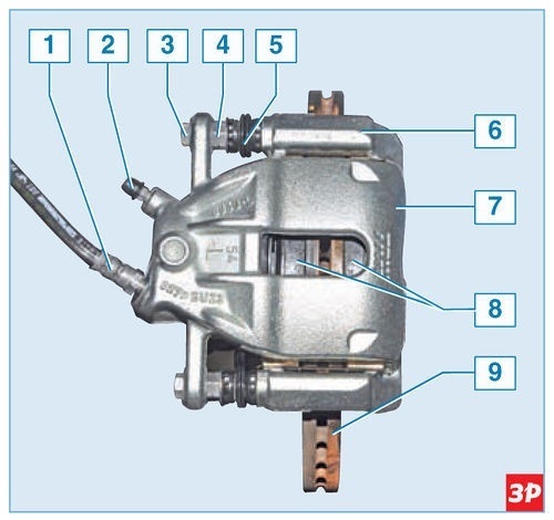
The brake mechanism of a forward wheel assy
1 - brake hose;
2 - fitting for bleeding the hydraulic brakes;
3 – a bolt of fastening of a support to a directing finger;
4 - guide pin;
5 - protective cover of the guide pin;
6 - guide pads;
7 - support;
8 - brake pads;
9 - brake disc.
The brake mechanism of the front wheels is disc, with a floating caliper, which includes a caliper made integral with a single-piston wheel cylinder.
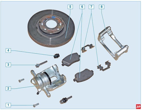
Front wheel brake elements
1 – a bolt of fastening of a support to a directing finger;
2 - support;
3 - guide pin;
4 - protective cover of the guide pin;
5 - brake disc;
6 - brake pads;
7 - pads of spring clips;
8 - guide pads.
The brake shoe guide is attached to the steering knuckle with two bolts, and the bracket is attached with two bolts to the guide pins installed in the guide shoe holes. Rubber protective covers are installed on the fingers. The holes for the guide shoe pins are filled with grease.
When braking, the fluid pressure in the hydraulic drive of the brake mechanism increases, and the piston, leaving the wheel cylinder, presses the inner brake pad against the disc. Then the carrier (due to the movement of the guide pins in the holes of the guide pads) moves relative to the disc, pressing the outer brake pad against it. A piston with a sealing rubber ring of rectangular cross section is installed in the cylinder body. Due to the elasticity of this ring, a constant optimal clearance between the disc and the brake pads is maintained.
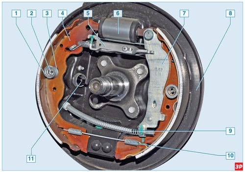
Rear wheel brake with drum removed
1 – spring cup;
2 - support column;
3 — pillows of a clamping spring;
4 - front block;
5 - spacer with a backlash regulator;
6 - working cylinder;
7 - rear brake shoe with parking brake lever;
8 - brake shield;
9 – a cable of a manual brake;
10 - lower connecting spring;
11 - ABS sensor.
The brake mechanism of the rear wheel is drum, with a two-piston wheel cylinder and two brake shoes, with automatic adjustment of the gap between the shoes and the drum. The brake drum is also the hub of the rear wheel and the bearing is pressed into it.
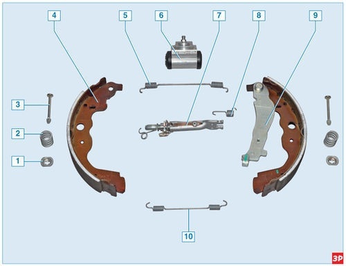
Elements of the brake mechanism of the rear wheel
1 – spring cup;
2 — pillows of a clamping spring;
3 - support column;
4 - front block;
5 - upper coupling spring;
6 - working cylinder;
7 - space;
8 - control spring;
9 – a back block with the lever of a drive of a parking brake;
10 - lower connecting spring.
The mechanism for automatic adjustment of the gap between the shoes and the drum consists of a composite gasket for the shoes, an adjusting lever and its spring. It starts to work when the gap between the brake pads and the brake drum increases.
When you press the brake pedal under the action of the pistons of the wheel cylinder, the pads begin to diverge and press against the drum, while the protrusion of the regulator lever moves along the cavity between the teeth of the ratchet nut. With a certain amount of wear on the pads and the brake pedal depressed, the adjusting lever has enough travel to turn the ratchet nut one tooth, thereby increasing the length of the spacer bar, as well as reducing the clearance between the pads and the drum.
Elements of the mechanism for automatic adjustment of the gap between the shoes and the drum
1 - twisted spring of the threaded tip;
2 - threaded tip spacers;
3 - regulator spring lever;
4 - space;
5 - crossbow;
6 - ratchet nut.
Thus, the gradual elongation of the shim automatically maintains the clearance between the brake drum and the shoes. The wheel cylinders of the brake mechanisms of the rear wheels are the same. The front brake pads of the rear wheels are the same, while the rear ones are different: they are non-removable levers installed symmetrically to the hand brake actuation mirror.
The spacer and ratchet nut of the brake mechanism of the left and right wheels are different.
The ratchet nut and spacer tip of the left wheel have left hand threads, while the ratchet nut and spacer tip of the right wheel have right hand threads. The levers of the regulators of the brake mechanisms of the left and right wheels are symmetrical.
ABS block
1 - control unit;
2 - hole for connecting the tube of the brake mechanism of the right front wheel;
3 - hole for connecting the tube of the brake mechanism of the left rear wheel;
4 - hole for connecting the tube of the brake mechanism of the right rear wheel;
5 - hole for connecting the tube of the brake mechanism of the left front wheel;
6 – an opening for connection of a tube of the main brake cylinder;
7 - pump;
8 - hydraulic block.
Some vehicles are equipped with an anti-lock braking system (ABS), which provides more effective braking of the vehicle by reducing the fluid pressure in the wheel brakes when they are locked.
The fluid from the master brake cylinder enters the ABS unit, and from there it is supplied to the brake mechanisms of all wheels.
Front wheel speed sensor
The ABS unit, installed in the engine compartment on the right side member near the dashboard, consists of a hydraulic unit, a modulator, a pump and a control unit.
ABS works based on signals from inductive-type wheel speed sensors.
Location of the front wheel speed sensor on the hub assembly
1 - overhead ring of the speed sensor;
2 - the inner ring of the wheel bearing;
3 – wheel speed sensor;
4 — column of the wheel;
5 - steering knuckle.
The front wheel speed sensor is located on the wheel hub assembly; it is inserted into the groove of a special ring for attaching the sensor, sandwiched between the end surface of the outer ring of the hub bearing and the shoulder of the steering knuckle hole for the bearing.
The rear wheel speed sensor is mounted on the brake casing, and the sensor transmission is a ring of magnetic material pressed onto the shoulder of the brake drum
The drive disk of the front wheel speed sensor is a hub bearing sleeve located on one of the two end surfaces of the bearing. This dark disc is made of magnetic material. On the other end surface of the bearing there is a conventional light-colored sheet metal shield.
When the vehicle is braked, the ABS control unit detects the start of the wheel lock and opens the corresponding modulating solenoid valve to release the pressure of the working fluid in the channel. The valve opens and closes several times per second, so you can tell if the ABS is working by a slight vibration in the brake pedal when braking.
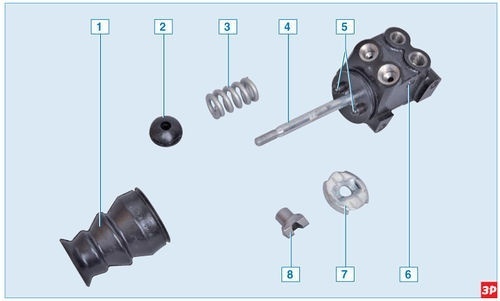
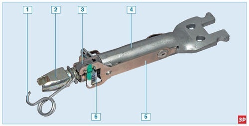
Rear wheel brake pressure regulator parts
1 - protective cover from dirt;
2 - support sleeve;
3 - spring;
4 - pressure regulator pin;
5 - pressure regulator pistons;
6 - pressure regulator housing;
7 - thrust washer;
8 - guide sleeve.
Some vehicles are not equipped with an anti-lock braking system (ABS). On these vehicles, brake fluid for the rear wheels is supplied through a pressure regulator located between the rear suspension beam and the body.
With an increase in the load on the rear axle of the car, the elastic control lever connected to the rear suspension beam is loaded, which transmits the force to the control piston. When the brake pedal is depressed, fluid pressure tends to push the piston out, which is prevented by the force of the elastic lever. When balancing the system, a valve located in the regulator shuts off the fluid supply to the wheel cylinders of the rear wheel brakes, preventing a further increase in the braking force on the rear axle and preventing the rear wheels from locking in front of the front rear wheels of the wheel. With an increase in the load on the rear axle, when the grip of the rear wheels with the road improves.
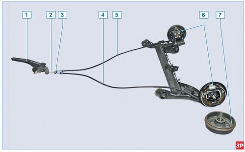
Parking brake elements
1 - lever;
2 - front wire;
3 - cable equalizer;
4 - left rear cable;
5 - right rear cable;
6 - brake mechanism of the rear wheel;
7 - drum.
Activation of the parking brake: manual, mechanical, cable, on the rear wheels. It consists of a lever, a front cable with an adjusting nut at the end, an equalizer, two rear cables and levers on the rear wheel brakes.
The parking brake lever, fixed between the front seats in the floor tunnel, is connected to the front cable. An equalizer is attached to the rear tip of the front cable, into the holes of which the front tips of the rear cables are inserted. The rear ends of the cables are connected to the parking brake levers attached to the rear shoes.
During operation (until the rear brake pads are completely worn out), it is not necessary to adjust the operation of the parking brake, since the lengthening of the brake strut compensates for the wear of the pads. The parking brake actuator should only be adjusted after the parking brake lever or cables have been replaced.