wooden steam engine
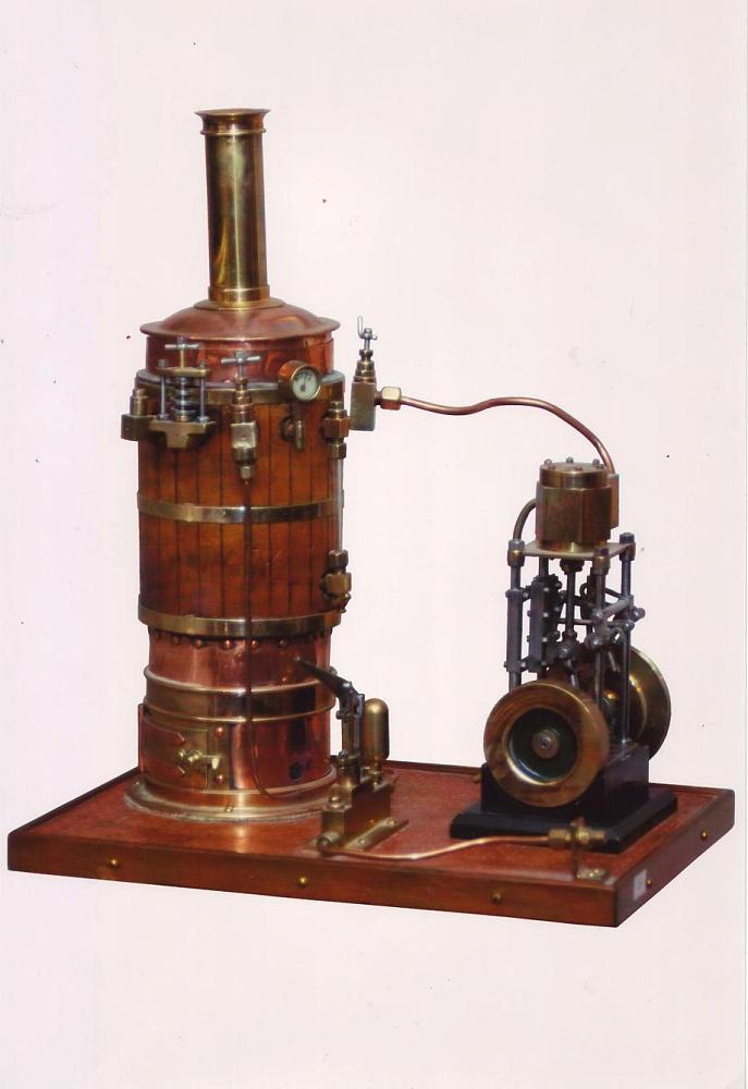
The first steam engines with a movable oscillating cylinder were created in the XNUMXth century and were used to propel small steam ships. Their advantages include the simplicity of construction. Of course, those steam engines were not made of wood, but of metal. They had few parts, they did not break down, and they were cheap to manufacture. They were made in a horizontal or vertical version so that they would not take up much space on the ship. These types of steam engines were also produced as working miniatures. They were steam-powered polytechnic toys.
The simplicity of the design of the oscillating cylinder steam engine is its great advantage, and we may be tempted to make such a model out of wood. We certainly want our model to work and not just stand still. It's achievable. However, we will not drive it with hot steam, but with ordinary cold air, preferably from a home compressor or, for example, a vacuum cleaner. Wood is an interesting and easy-to-work material, so you can recreate the mechanism of a steam engine in it. Since, when building our model, we provided for the side split part of the cylinder, thanks to this we can see how the piston works and how the cylinder moves relative to the timing holes. I suggest you get to work immediately.
Machine operation steam with a rocking cylinder. We can analyze them for Photo 1 on a series of photographs marked from a to f.
- Steam enters the cylinder through the inlet and pushes the piston.
- The piston rotates the flywheel through the piston rod and the connecting rod crank.
- The cylinder changes its position, as the piston moves, it closes the inlet and opens the steam outlet.
- The piston, driven by the inertia of the accelerating flywheel, pushes the exhaust steam through this hole, and the cycle starts over.
- The cylinder changes position and the inlet opens.
- The compressed steam again passes through the inlet and pushes the piston.
Tools: Electric drill on a stand, drill attached to a workbench, belt sander, vibratory grinder, dremel with woodworking tips, jigsaw, glutering machine with hot glue, M3 die with threading chuck, carpentry drill 14 millimeters. We will use a compressor or a vacuum cleaner to drive the model.
Materials: pine board 100 by 20 millimeters wide, roller 14 millimeters in diameter, board 20 by 20 millimeters, board 30 by 30 millimeters, board 60 by 8 millimeters, plywood 10 millimeters thick. Silicone grease or machine oil, a nail with a diameter of 3 millimeters and a length of 60 millimeters, a strong spring, a nut with an M3 washer. Clear varnish in an aerosol can for varnishing wood.
Machine base. We will make it from a board measuring 500 by 100 by 20 millimeters. Before painting, it is good to level out all the irregularities of the board and the places left after cutting with sandpaper.
Flywheel support. We cut it out of a pine board measuring 150 by 100 by 20 millimeters. We need two identical elements. After rounding with a belt grinder, sandpaper 40 along the upper edges in the arcs and processing with fine sandpaper in the supports, drill holes with a diameter of 14 millimeters in the places as shown in fig. Photo 2. The height of the carriage between the base and the axle is to be greater than the radius of the flywheel.
Flywheel rim. We will cut it out of plywood 10 millimeters thick. The wheel has a diameter of 180 millimeters. Draw two identical circles on the plywood with a caliper and cut them out with a jigsaw. On the first circle, draw a circle with a diameter of 130 millimeters coaxially and cut out its center. This will be the flywheel rim, that is, its rim. A wreath to increase the inertia of a spinning wheel.
Flywheel. Our flywheel has five spokes. They will be created in such a way that we will draw five triangles on the wheel with rounded edges and rotated 72 degrees with respect to the wheel axis. Let's start by drawing a circle with a diameter of 120 millimeters on paper, followed by knitting needles 15 millimeters thick and circles at the corners of the resulting triangles. You can see it on Photo 3. i 4., where the design of the wheel is shown. We put the paper on the cut out circles and mark the centers of all the small circles with a hole punch. This will ensure drilling accuracy. We drill all the corners of the triangles with a drill with a diameter of 14 millimeters. Since a blade drill can ruin plywood, it is recommended that you only drill half the thickness of the plywood, then turn the material over and finish drilling. A flat drill of this diameter ends with a tiny protruding shaft that will allow us to accurately locate the center of the drilled hole on the other side of the plywood. Reflecting on the superiority of carpentry cylindrical drills over flat carpentry, we cut off the remaining unnecessary material from the flywheel with an electric jigsaw to obtain effective knitting needles. Dremel compensate for any inaccuracies and round the edges of the spokes. Glue the wreath circle with vicola glue. We drill a hole with a diameter of 6 millimeters in the center in order to insert an M6 screw in the center, thus obtaining an approximate axis of rotation of the wheel. After installing the bolt as the axis of the wheel in the drill, we process the rapidly rotating wheel, first with coarse-grained and then with fine sandpaper. I advise you to change the direction of rotation of the drill so that the wheel bolt does not loosen. The wheel should have even edges and rotate evenly after processing, without hitting the side. When this is achieved, we disassemble the temporary bolt and drill a hole for the target axle with a diameter of 14 millimeters.
Connecting rod. We will cut it out of plywood 10 millimeters thick. To make the job easier, I suggest starting by drilling two 14mm holes 38mm apart, and then sawing out the final classic shape, as shown in Photo 5.
flywheel axle. It is made of a shaft with a diameter of 14 millimeters and a length of 190 millimeters.
Shaft axle. It is cut from a shaft with a diameter of 14 millimeters and a length of 80 millimeters.
Cylinder. We will cut it out of plywood 10 millimeters thick. It consists of five elements. Two of them measure 140 by 60 millimeters and are the side walls of the cylinder. Bottom and top 140 by 80 millimeters. The lower part of the cylinder measures 60 by 60 and is 15 millimeters thick. These parts are shown in Photo 6. We glue the bottom and sides of the cylinder with braided glue. One of the conditions for the correct operation of the model is the perpendicularity of the gluing of the walls and bottom. Drill holes for the screws in the top of the cylinder cover. We drill holes with a 3 mm drill so that they fall into the center of the wall thickness of the cylinder. Drill some holes in the cover with an 8mm drill so the screw heads can hide.
Piston. Its dimensions are 60 by 60 by 30 millimeters. In the piston, we drill a central blind hole with a diameter of 14 millimeters to a depth of 20 millimeters. We will insert the piston rod into it.
Piston rod. It is made of a shaft with a diameter of 14 millimeters and a length of 320 millimeters. The piston rod ends on one side with a piston, and on the other side with a hook on the axis of the connecting rod crank.
Connecting rod axle. We will make it from a bar with a section of 30 by 30 and a length of 40 millimeters. We drill a 14 mm hole in the block and a second blind hole perpendicular to it. We will glue the other free end of the piston rod into this hole. Clean the inside of the through hole and sand it with fine sandpaper rolled into a tube. The connecting rod axle will rotate in the bore and we want to reduce friction at that point. Finally, the handle is rounded off and finished with a wood file or a belt sander.
Timing Bracket. We will cut it out of a pine board measuring 150 by 100 by 20. After sanding in the support, drill three holes in the places as shown in the picture. The first hole with a diameter of 3 mm for the timing axis. The other two are the air inlet and outlet of the cylinder. The drilling point for all three is shown in Photo 7. When changing the dimensions of machine parts, the drilling sites must be found empirically by pre-assembling the machine and determining the upper and lower positions of the cylinder, namely the location of the hole drilled in the cylinder. The place where the timing will work is sanded with an orbital sander with fine paper. It should be even and very smooth.
Swinging timing axle. Blunt the end of a 60 mm long nail and round it off with a file or grinder. Using an M3 die, cut its end about 10 millimeters long. To do this, choose a strong spring, M3 nut and washer.
Distribution. We will make it from a strip measuring 140 by 60 by 8 millimeters. Two holes are drilled in this part of the model. The first is 3 millimeters in diameter. We will put a nail in it, which is the axis of rotation of the cylinder. Remember to drill this hole in such a way that the nail head is completely recessed into the wood and does not protrude above its surface. This is a very important moment in our work, affecting the correct operation of the model. The second 10mm diameter hole is the air inlet / outlet. Depending on the position of the cylinder in relation to the holes in the timing bracket, air will enter the piston, pushing it, and then being forced out by the piston in the opposite direction. Glue the timing with the glued-in nail that acts as the axle to the cylinder surface. The axis should not wobble and should be perpendicular to the surface. Finally, drill a hole in the cylinder using the location of the hole in the timing board. All irregularities of the wood, where it will be in contact with the timing support, are smoothed with an orbital sander with fine sandpaper.
Machine assembly. Glue the flywheel axle supports to the base, being careful that they are in line and parallel to the plane of the base. Before complete assembly, we will paint the elements and components of the machine with a colorless varnish. We put the connecting rod on the flywheel axis and glue it exactly perpendicular to it. Insert the connecting rod axle into the second hole. Both axes must be parallel to each other. Glue wooden reinforcing rings to the flywheel. In the outer ring, insert a wood screw into the hole that secures the flywheel to the flywheel axle. On the other side of the base, glue the cylinder support. Lubricate all wooden parts that will move and come into contact with each other with silicone grease or machine oil. Silicone should be lightly polished to minimize friction. The correct operation of the machine will depend on this. The cylinder is mounted on the carriage so that its axis protrudes beyond the timing. You can see it on Photo 8. Put the spring on the nail protruding beyond the support, then the washer and secure the whole thing with a nut. The cylinder, pressed by a spring, should move slightly on its axis. We put the piston in its place into the cylinder, and put the end of the piston rod on the connecting rod axle. We put the cylinder cover on and fasten it with wood screws. Lubricate all cooperating parts of the mechanism, especially the cylinder and the piston, with machine oil. Let's not regret the fat. The wheel moved by hand should rotate without any felt resistance, and the connecting rod should transfer the movement to the piston and cylinder. Photo 9. Insert the end of the compressor hose into the inlet and turn it on. Turn the wheel and the compressed air will move the piston and the flywheel will start spinning. The critical point in our model is the contact between the timing plate and its stator. Unless most of the air escapes this way, a properly designed car should move easily, giving DIY enthusiasts a lot of fun. The cause of the malfunction may be too weak a spring. After a while, the oil soaks into the wood and the friction becomes too much. It also explains why people didn't build steam engines out of wood. However, the wooden engine is very efficient, and the knowledge of how the oscillating cylinder works in such a simple steam engine remains for a long time.
wooden steam engine