Great Wall 4G63S4M engine
Content
The Great Wall 4G63S4M power unit incorporates four cylinders arranged side by side, a gas distribution mechanism, with an overhead camshaft and 16 valves. It also has liquid cooling and a distributed fuel injection system.
The maximum power of the stock version of the engine is 116 hp and 175 Nm of torque. The engine number is located near the exhaust manifold, on the cylinder block.
There is also a factory modification of this engine with a turbine. It develops a power of 150 hp. and a torque of 250 Nm. It was created jointly with Mitsubishi, a subsidiary located in Shanghai Shanghai MHI Turbocharger Co. It operates on gasoline fuel with 92 octane rating.
Together with them, a manual gearbox works, with five or six steps. Automatic transmission was not installed at all. The drive of the rear wheels is carried out constantly. The front wheels are connected only when overcoming difficult sections. Also, in all cars of this model there is no differential, the connection is of a rigid type.
The service brake system has two circuits separated along the axes. They are driven by a hydraulic system, which has a vacuum booster. There are disc brakes in the front, and disc brakes with ABS and EBD sensors in the back. Rack and pinion steering with hydraulic booster. In front of the car, an independent double wishbone suspension is installed. It contains hydraulic shock absorbers, with anti-roll bars. A dependent suspension is installed at the rear. It has hydraulic telescopic shock absorbers.
The installation of this internal combustion engine was carried out on two generations of the GW Hover H3 car, starting in 2010. In the Russian automotive market, this model is very popular due to its price, good quality and relatively modern design and technical equipment. The atmospheric engine with the index 4G63S4M is the most common on these vehicles.
It lends itself well to chip tuning and various upgrades, thanks to which you can achieve a power of 177 hp. and a torque of 250 Nm. With careful operation and the use of only high-quality lubricants and fuels, the Great Wall engine life is more than 250 thousand km.
Great Wall 4G63S4M power plants are reliable units. Of the sores, one can distinguish the appearance of noise from the input shaft bearing. It is eliminated by simply replacing the product with a new one.
Technical specifications
| Dimensions and weight | |
|---|---|
| Length/width/height, mm. | 4650/1800/1810 |
| Wheelbase size, mm. | 2700 |
| The volume of the fuel tank, l. | 74 |
| The size of the front and rear track, mm. | 1515/1520 |
| Engine and transmission | |
| Motor marking | Mitsubishi 4G63D4M |
| engine's type | 4-cylinder with 16 valves |
| Engine displacement, l. | 2 |
| Developed power hp (kW) at rpm | 116 (85) at 5250 |
| Maximum torque Nm at rpm. | 170 at 2500-3000 |
| Environmental class | Euro 4 |
| type of drive | Rear and plug-in full |
| Transmission | Manual transmission with 5 or 6 steps |
| performance | |
| Maximum travel speed km/h. | 160 |
| Road clearance height, mm. | 180 |
| Average fuel consumption, l / 100 km | 7.2 |
Design features
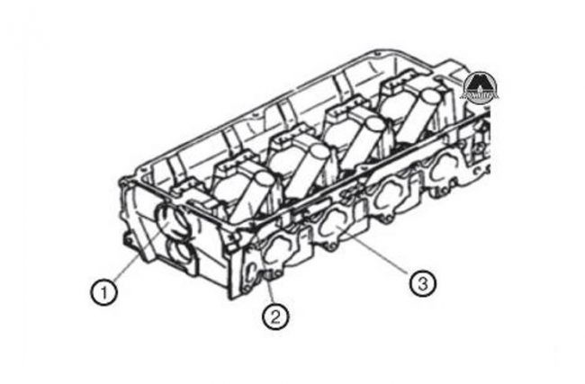
- Hole for bearing
- candle tube;
- Channel lets in.
The cylinder head is made of aluminium. Its fastening to the block is carried out with the help of bolts. A metal-asbestos gasket is installed between the contacting surfaces of the block and the head. The required sealing is ensured by the preload. When calculating the force of this tightness, the difference in linear expansions of the bolted elements and the cylinder head must be taken into account.
The head is equipped with inlet and outlet channels, coolant ducts, jumpers with a socket for the rocker axle. Special heat-resistant cast iron is the material for the seat and bushing.
Lubrication of the support seats located on the camshaft is carried out under pressure. Achieving the required surface frequency and the same volume of working chambers is carried out by machining the surface of the cylinder head, which is adjacent to the block.
Block device
The cylinder block of this engine is cast iron. It is one with the cylinders. Ensuring intensive heat removal is carried out due to special coolant ducts located around the entire perimeter of the cylinders.
It also contributes to the effective cooling of the piston system, lowering the temperature of the lubricating fluid, as well as reducing the deformation of the BC, from temperature unevenness in various parts of the block. Throughout the entire period of operation, it is necessary to periodically check the tightening of bolted joints and nuts, to monitor the tightness of the crankshaft mounting seal and joints in which gaskets are present.
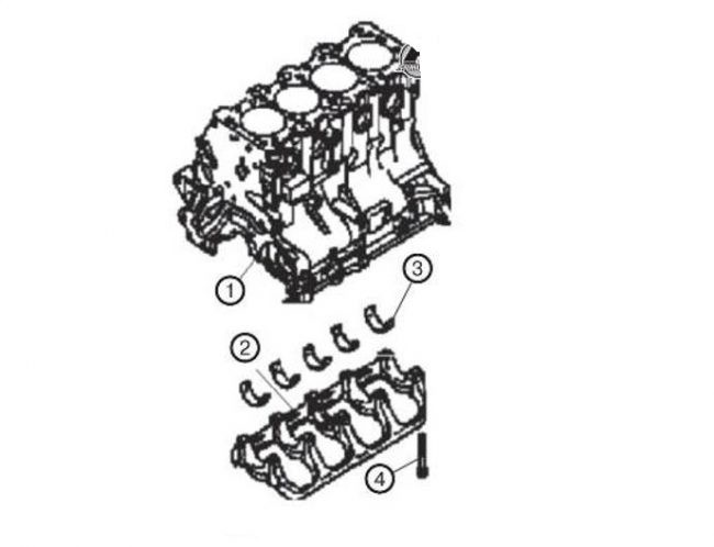
- Cylinder block;
- The cover on which the main bearings are located;
- Inserts;
- cover bolt;
The location of the channels through which the lubricant is supplied to the block and cylinder head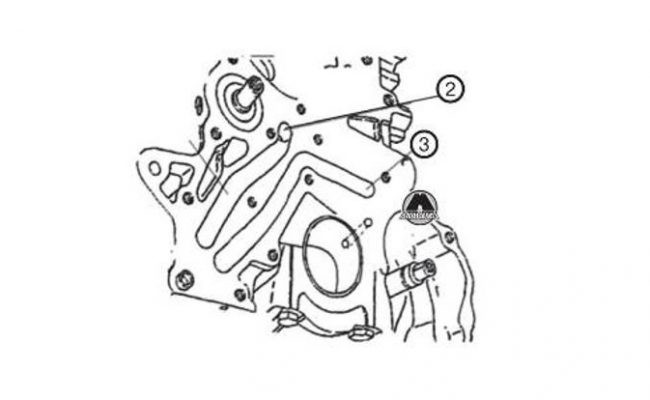
- The channel connecting the oil filter and the main channel;
- Main oil channel;
- Underwater channel connecting the oil pump and oil filter.
Cylinder head lubrication scheme:
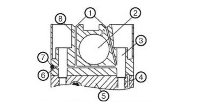
- Oil circulation channels
- Camshaft bearing hole
- Hole for the cylinder head bolt;
- Vertical BC oil circulation channel;
- Cylinder block;
- Horizontal oil circulation channel;
- plug;
- Cylinder head.
The location of the vertical oil channels that provide the supply of lubricating fluid to the gas distribution mechanism is the rear of the cylinder head.
End cap located on the front side
The manufacturing material is aluminum alloy. The front end cap is the front end of the oil pump unit. The place of attachment of the front crankshaft seal, pump seal and balancing shaft is the outer side of the rear cover. The upper and lower balancing shafts are fastened by the rear cover. The lower balancing shaft is used as the driven shaft of the oil pump.
Crankshaft
The engine has a full-bearing type crankshaft. It is cast from special high-strength cast iron.
The main journals have a diameter of 57 mm. The nominal diameter of the connecting rod journals of the crankshaft is 45 mm. With the help of high-frequency currents, the working surfaces of the necks are hardened in order to increase the wear resistance. Also, before installation, the crankshaft is dynamically balanced. It contains channels for the circulation of engine oil. With the help of plugs, the technological outputs of these channels are plugged.
The piston stroke indicator is 88 mm. Uninterrupted circulation of the oil fluid and shock-free operation of the connection is ensured by the clearance of the knee necks and liners. The crankshaft is fixed with thrust half rings. The sealing of the toe and rear flange is carried out using cuffs.
Piston
The pistons are cast from aluminum alloy using a thermostatic ring. Piston skirts are of a non-split type. To prevent the pistons from hitting the valves, special grooves are made. This can happen while adjusting the gas distribution mechanism. Also in the pistons there are three grooves in which the piston rings are installed.
The top two slots are for the compression rings, and the bottom slot is for the oil scraper ring. The internal cavity of the pistons is connected to the lower groove by means of a special hole through which excess oil enters and then they are drained into the oil sump.
Automatic tensioner
The purpose of the automatic tensioner is to tension the drive belt. This eliminates the possibility of belt slippage and disruption of the gas distribution phases. The shear rate should be less than 11mm when the working force is 98-196mm. The indicator of the protrusion of the pusher is 12 mm.
Gas distribution mechanism
This mechanism regulates the intake of the fuel-air mixture into the working cavity of the cylinders, as well as the release of exhaust gases from them. This process is carried out in accordance with the operating mode of the piston group. The cylinder head incorporates valves, one-piece type. A special hardfacing is used to make the surface of the valve belt that comes into contact with the valve seat.
In this engine, the camshaft is located on top, as is the location of the valves. The protrusions of crackers are placed in special ring-shaped grooves, the location of which is the upper part of the rods.
The valve guide bushings, in which the rods are moved, are pressed into the cylinder head. Sleeve holes are finished after a high-precision pressing process.
The installation of oil seals, which are put on the upper surface of the bushings, excludes the possibility of oil fluid penetrating into the gap between the valves and bushings. The material for the manufacture of oil seals is heat-resistant rubber. Due to the high precision of the seat finish, which is carried out after the pressing process, the valves fit very tightly in their seats. There should be a mark on the top of the spring.
The axis of the rocker arms is made of steel and has holes that are designed to supply oil to the camshaft journals. Rocker necks are also hardened. The rocker arm axle stopper is made by means of a screw. The screw plug covers the hole for the axle. The rocker arms are made of aluminum alloy, which reduces the weight of the motor unit. This contributes to the fact that the load on the camshaft cams is reduced, and as a result, the service life of these elements is increased. The performance of the engine is also improved, and the consumption of fuel fluid is reduced. The axial movement of the rocker arm is limited by washers and springs.
Labels for regulating the gas distribution mechanism
There are 38 teeth in the gear of the crankshaft of the balancing mechanism, while there are only 19 of them on the gear of the left balancing shaft. To install the timing belt, it is necessary to align all the marks, in accordance with the figures below.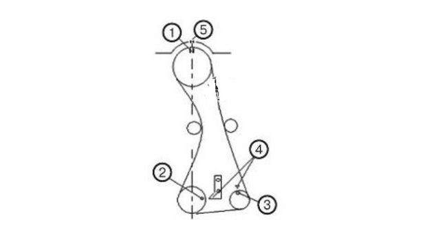
- Camshaft pulley mark;
- crankshaft pulley mark;
- Oil pump gear mark;
- End cap label;
- Cylinder head cover label.

