Mercedes-Benz M275 engine
The M275 series of engines replaced the structurally obsolete M137. Unlike its predecessor, the new engine used cylinders with a smaller diameter, two channels for coolant circulation, an improved fuel supply and control system ME 2.7.1.
Description of M275 engines
Thus, the differences between the new internal combustion engine are as follows:
- the dimensions of the cylinders in the circumference were reduced to 82 mm (on the M137 it was 84 mm), which made it possible to reduce the working volume to 5,5 liters and thicken the free space between the elements of the CPG;
- an increase in the partition, in turn, made it possible to make two channels for the circulation of antifreeze;
- the ill-fated ZAS system, shutting off several cylinders at light engine load and adjusting camshaft exposure, has been completely eliminated;
- the electronic engine management system has been replaced with a more modernized version;
- the DMRV was abolished - two regulators were used instead;
- removed 4 lambda probes, which gave greater efficiency to the engine;
- for better fuel pressure regulation, the fuel pump was combined with a control unit and a simple filter - an unmanaged fuel pump was installed on the M137, including a combined sensor;
- the heat exchanger inside the cylinder block was removed, and a conventional radiator was installed in its place at the front;
- a centrifuge has been added to the exhaust ventilation system;
- compression reduced to 9.0;
- a scheme was used with two turbines embedded in the exhaust manifolds - the boost is cooled by two channels located on top of the cylinder head.
However, the M275 uses the same 3-valve layout that worked well on the M137.
Read more about the difference between M275 and M137 engines.
| M275 with ME2.7.1 | M137 with ME2.7 |
| Charge air pressure detection via a signal from a pressure sensor upstream of the throttle actuator. | no |
| Load recognition by means of a signal from a pressure sensor downstream of the throttle actuator. | no |
| no | Hot-wire air mass meter with integrated sensor intake air temperature. |
| For each row of cylinders, a turbocharger (Biturbo) is cast steel. | no |
| The turbine housing is integrated into the exhaust manifold, the axle housing is cooled by coolant. | no |
| Boost pressure regulation by means of a pressure converter, boost pressure regulation and via controlled diaphragm pressure regulators (Wastgate-Ventile) in the turbine housings. | no |
| Controlled by changeover valve. Turbocharger noise is prevented by rapidly reducing the boost pressure when going from full load to idle mode. | no |
| One liquid charge air cooler per turbocharger. Both liquid charge air coolers have their own low temperature cooling circuit with low temperature radiator and electric circulation pump. | no |
| Each row of cylinders has its own air filter. After each air filter, a pressure sensor is located in the air filter housing to detect the pressure drop across the air filter. In order to limit the maximum speed of the turbocharger, the compression ratio after/before the turbocharger is calculated and controlled according to the characteristics by controlling the boost pressure. | One air filter. |
| There is one catalyst for each row of cylinders. A total of 4 oxygen sensors, respectively before and after each catalyst. | For every three cylinders, one front catalyst. A total of 8 oxygen sensors, respectively before and after each front catalyst |
| no | Camshaft position adjustment by engine oil, 2 camshaft position adjustment valves. |
| no | Disabling the cylinders of the left row of cylinders. |
| no | Oil pressure sensor after additional oil pump for cylinder deactivation system. |
| no | Exhaust gas damper in the exhaust manifold for the cylinder deactivation system. |
| Ignition system ECI (variable voltage ignition with integrated ion current measurement), ignition voltage 32 kV, two spark plugs per cylinder (dual ignition). | Ignition system ECI (Variable Voltage Ignition with Integrated Ion Current Sensing), ignition voltage 30 kV, two spark plugs per cylinder (dual ignition). |
| Misfire detection by measuring the ion current signal and by evaluating engine smoothness with a crankshaft position sensor. | Misfire detection by measuring the ion current signal. |
| Detonation detection by means of 4 knock sensors. | Detonation detection by measuring the ion current signal. |
| Atmospheric air pressure sensor in the ME control unit. | no |
| Regeneration pipeline with non-return valve to prevent boost pressure from entering the activated carbon tank. | Regeneration pipeline for atmospheric engine without non-return valve. |
| The fuel system is made according to a single-line scheme, the fuel filter with an integrated membrane pressure regulator, the fuel supply is regulated depending on the need. The fuel pump (maximum output approx. 245 l/h) is controlled by a PWM signal from the fuel pump control unit (N118) corresponding to the signals from the fuel pressure sensor. | The fuel system is made in a single-line circuit with an integrated membrane pressure regulator, the fuel pump is not controlled. |
| 3-piece exhaust manifold with integrated turbine housing. | The exhaust manifold is enclosed in a sealed heat and noise insulating casing with an air gap. |
| Engine crankcase ventilation with centrifugal type oil separator and pressure control valve. Non-return valve in crankcase ventilation lines for partial and full load. | Simple crankcase ventilation. |
M275 systems
Now about the systems of the new engine.
- Timing chain drive, two-row. In order to reduce noise, rubber is used. It covers parasitic and crankshaft sprockets. Hydraulic tensioner.
- The oil pump is two-stage. It is driven by a separate chain equipped with a spring.
- The electronic motor control system is not much different from the ME7. version used on its predecessor. The main parts are still the central module and coils. The new ME 2.7.1 system downloads information from four knock sensors - this is a signal for shifting the PTO towards late ignition.
- The boost system is connected to the exhaust. The compressors are adjusted using airless components.
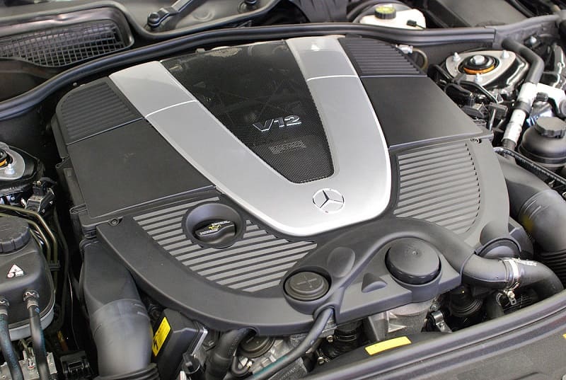
The M275 engine is built in a V-shape. It is one of the successful twelve-cylinder units, comfortably placed under the hood of the car. The motor block is molded from lightweight refractory material. Upon direct examination, it turns out that the design of the internal combustion engine is extremely difficult to manufacture most of the channels and supply pipes. The M275 has two cylinder heads. They are also made of winged material, have two camshafts in each.
In general, the M275 engine has the following advantages over its predecessor and other similar class engines:
- good resistance to overheating;
- less noise;
- excellent indicators of CO2 emissions;
- low weight with high stability.
Turbocharger
Why was a turbocharger installed on the M275 instead of a mechanical one? Firstly, it was forced to do by modern trends. If earlier there was a demand for a mechanical supercharger because of a good image, today the situation has changed radically. Secondly, the designers managed to solve the problem of compact placement of the engine under the hood - and they used to think so - the turbocharger requires a lot of space, so installation on the base engine is impossible due to layout features.
The advantages of a turbocharger are immediately noticeable:
- rapid build-up of pressure and engine response;
- eliminating the need to connect to the lubrication system;
- simple and flexible release layout;
- no heat loss.
On the other hand, such a system is not without drawbacks:
- expensive technology;
- mandatory separate cooling;
- increase in engine weight.
Modifications
The M275 engine has only two working versions: 5,5 liters and 6 liters. The first version is called M275E55AL. It produces about 517 hp. With. The second option with increased volume is M275E60AL. The M275 was installed on premium Mercedes-Benz models, however, like its predecessor. These are cars of class S, G and F. Modified engineering and technical solutions of the past have been successfully applied in the design of the engines of the series.
The 5,5-liter unit was installed on the following Mercedes-Benz models:
- 3rd generation coupe CL-Class 2010-2014 and 2006-2010 on the C216 platform;
- restyled 2nd generation coupe CL-Class 2002-2006 on the C215 platform;
- 5th generation sedan S-Class 2009-2013 and 2005-2009 W221;
- restyled sedan 4th generation S-Class 2002-2005 W
A 6-liter for:
- 3rd generation coupe CL-Class 2010-2014 and 2006-2010 on the C216 platform;
- restyled 2nd generation coupe CL-Class 2002-2006 on the C215 platform;
- restyled SUVs of the 7th generation G-Class 2015-2018 and 6th generation 2012-2015 on the W463 platform;
- 5th generation sedan S-Class 2009-2013 and 2005-2009 on the W221 platform;
- restyled sedan 4th generation S-Class 2002-2005 W
| Engine displacement, cc | 5980 and 5513 |
| Maximum torque, N * m (kg * m) at rpm. | 1,000 (102) / 4000; 1,000 (102) / 4300 and 800 (82) / 3500; 830 (85) / 3500 |
| Maximum power, hp | 612 - 630 and 500 - 517 |
| Fuel used | Gasoline AI-92, AI-95, AI-98 |
| Fuel consumption, l / 100 km | 14,9-17 and 14.8 |
| engine's type | V-shaped, 12-cylinder |
| Add. engine information | SOHC |
| CO2 emission in g / km | 317 - 397 and 340 - 355 |
| Cylinder diameter, mm | 82.6 – 97 |
| Number of valves per cylinder | 3 |
| Maximum power, h.p. (kW) at rpm | 612 (450) / 5100; 612 (450) / 5600; 630 (463) / 5000; 630 (463) / 5300 and 500 (368) / 5000; 517 (380) / 5000 |
| Supercharger | Twin turbocharging |
| Compression ratio | 9-10,5 |
| Piston stroke length | 87 mm |
| Cylinder liners | Alloyed with Silitec technology. The thickness of the alloyed layer of the cylinder wall is 2,5 mm. |
| Cylinder block | Upper and lower parts of the cylinder block (die-cast aluminium). There is a rubber seal between the bottom part of the cylinder block and the upper part oil pan. The cylinder block consists of two parts. The dividing line runs along the center line of the crankshaft shaft. Thanks to the massive inserts for the crankshaft main bearings made of gray cast iron noise characteristics have been improved in the lower part of the business center. |
| Crankshaft | Crankshaft of optimal weight, with balancing masses. |
| Oil pan | The upper and lower parts of the oil pan are made of die-cast aluminium. |
| Connecting rods | Steel, forged. For normal operation under high loads, for the first time, high-strength forging material. On M275 engines, as well as on M137, the lower head of the connecting rod is made with a line fracture using “broken crank” technology, which improves the accuracy of the fit connecting rod caps when installing them. |
| Cylinder head | Aluminum, 2 pieces, made using the already known 3-valve technology. Each bank of cylinders has one camshaft, which controls the operation both intake and exhaust valves |
| Chain drive | The camshaft is driven by the crankshaft via a two-row roller chain. An asterisk is installed in the center of the collapse of the cylinder block to deflect the chain. In addition, the chain is guided by slightly curved shoes. The chain tension is carried out by means of a hydraulic chain tensioner through the shoe tensioner. Sprockets of the crankshaft, camshafts, as well as the guide sprocket rubberized to reduce chain drive noise. Oil pump drive positioned behind chain to optimize overall length Timing. The oil pump is driven by a single row roller chain. |
| Блок управления | ME 2.7.1 is an electronic engine management system upgraded from ME 2.7 M137 engine, which had to be adapted to new conditions and engine functions M275 and M285. The ME control unit contains all engine control and diagnostic functions. |
| Fuel system | Made in a single-wire circuit to avoid temperature rise in the fuel tank. |
| Fuel pump | Screw type, with electronic regulation. |
| Fuel filter | With integrated bypass valve. |
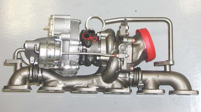
| Turbocharger | With steel die-cast housing, compactly integrated into an exhaust manifold. Each WGS (Waste Gate Steuerung) controlled turbocharger for the respective cylinder bank supplies fresh air to the engine. The turbine wheel in the turbocharger driven by the flow of spent gases. Fresh air enters through the intake pipe. Forcing wheel rigidly connected to the turbine wheel through the shaft, compresses the fresh air. The charge air is supplied through the pipeline to the engine. |
| Pressure sensors after air filter | There are two of them. They are located on the air housing filter between air filter and turbocharger on the left/right side of the engine. Purpose: to determine the actual pressure in the intake pipe. |
| Pressure sensor before and after throttle actuator | Located respectively: on the throttle actuator or in the intake pipe in front of the mains ECI power supply. determines the current boost pressure after the actuating throttle mechanism. |
| Boost pressure regulator pressure converter | It is located after the air filter on the left side of the engine. Conducts depending on control modulated boost pressure to membrane regulators. |

