Wiring diagram VAZ 2101: what hides the wiring with a fifty-year history
Content
The vast territory of the Soviet Union hindered the technical and social development of the country. In the open sale, there was no necessary number of cars for everyone who dreamed of personal transport. To meet demand, the country's leadership made an original decision: the Fiat 124 model was chosen as the prototype of the domestic vehicle, as the best car of 1967. The first version of the passenger car was called VAZ 2101. The design of the model, based on the design of Italian Fiat engineers, already at the production stage was awarded the Golden Mercury international award for its contribution to the development of society.
Wiring diagram VAZ 2101
The compact VAZ 2101 sedan differs from its Italian counterpart in a modified design for the conditions of hard gravel roads. For reliable operation of the “penny”, the engineers subjected the transmission, chassis, brake drums to transformations and strengthened the clutch basket. The electrical equipment of the first model of the Volga Automobile Plant was kept from the original, as it met the requirements and technical conditions of operation.
Wiring diagram VAZ 2101 (carburetor)
The engineers of the first Zhiguli used a standard single-wire circuit for connecting consumers of electrical energy. A “positive” wire with an operating voltage of 12 V is suitable for all devices, sensors and lamps. The second “negative” wire from the battery and the generator connects current consumers through the metal body of the car.
The composition of the electrical system
Essential elements:
- sources of electricity;
- current consumers;
- relays and switches.
From this list, a wide range of main sources and consumers of current is distinguished:
- Power supply system with battery, generator and voltage regulator.
- Engine starting system with electric starter.
- An ignition system that combines several elements: an ignition coil, a contact breaker, a switch, spark plugs and spark plug wires.
- Lighting with lamps, switches and relays.
- Control lamps on the instrument panel and sensors.
- Other electrical equipment: glass washer, windshield wipers, heater motor and horn.
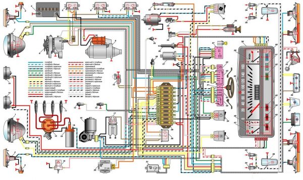
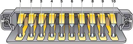
The position numbers of the elements of the electrical circuit on the general diagram of the VAZ 2101:
- Headlights.
- Front direction indicators.
- Side direction indicators.
- Accumulator battery.
- The relay of a control lamp of a charge of the accumulator.
- Relay for dipped headlights.
- Relay for turning on the high beam headlights.
- Generator.
- Starter.
- Hood lamp.
- Spark plug.
- Oil pressure warning light sensor.
- Coolant temperature gauge sensor.
- Sound signals.
- Distributor.
- Windshield wiper motor.
- Sensor of a control lamp of level of a brake liquid.
- Ignition coil.
- Windshield washer motor.
- Voltage regulator.
- Heater motor.
- Glove box lighting lamp.
- Additional resistor for the heater motor.
- Plug socket for portable lamp.
- The switch of a control lamp of a parking brake.
- Stop signal switch.
- Relay-interrupter of direction indicators.
- Reversing light switch.
- Fuse box.
- The relay-breaker of a control lamp of a parking brake.
- Wiper relay.
- Heater motor switch.
- Cigarette lighter
- Light switches located in the rear door pillars.
- Light switches located in the front door pillars.
- Plafonds.
- The ignition switch.
- A combination of devices.
- Coolant temperature gauge.
- Control lamp high beam headlights.
- Control lamp for outdoor lighting.
- Control lamp of indexes of turn.
- Battery charge indicator lamp.
- Oil pressure warning lamp.
- Parking brake and brake fluid level warning lamp.
- Fuel level indicator.
- Fuel reserve control lamp.
- Instrument cluster lighting lamp.
- Headlight switch.
- Turn signal switch.
- Horn switch.
- Windshield washer switch.
- Wiper switch.
- Outdoor lighting switch.
- Instrument lighting switch.
- Level indicator and fuel reserve sensor.
- Trunk lighting lamp.
- Rear lights.
- License plate light.
- Reversing lamp.
The operation of electrical systems depends on the contact of current sources and consumers with each other. Tight contact is ensured by quick-disconnect plugs at the ends of the wires. The maximum fit of the contact groups excludes the penetration of water and moisture. Responsible points of connection of wires to the battery, body, generator and starter are clamped with nuts. Reliable connection excludes oxidation of contacts.
Voltage sources
In the overall circuit of electrical cells, the battery and the alternator are the main sources of voltage in the car. Without a battery, the engine will not start, without a generator, all lighting sources and electrical appliances will stop working.
The operation of all systems begins with the battery. When the key is turned, a powerful flow of energy flows through the wires from the battery to the starter traction relay and through the body, which is used as the “mass” of the electrical circuit.
When turned on, the starter draws a lot of current. Do not hold the key in the "starter" position for a long time. This will prevent battery drain.
After starting the engine, the current from the generator feeds other consumers. The voltage supplied by the generator depends on the number of revolutions of the crankshaft, the current strength depends on the number of connected consumers. To maintain the required current parameters, a voltage regulator is installed.
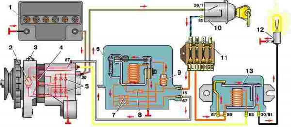
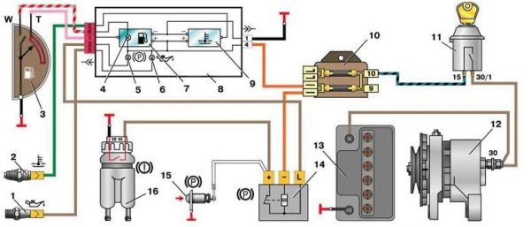
The position numbers of the electrical circuit elements on the generator connection diagram:
- Battery.
- Winding of the generator rotor.
- Generator.
- Generator stator winding.
- Generator rectifier.
- Voltage regulator.
- Additional resistors.
- temperature compensating resistor.
- Throttle.
- The ignition switch.
- Fuse box.
- Charge control lamp.
- Charge control lamp relay.
If the starter is defective, the engine cannot be started. You can get around this damage in the VAZ 2101 system if you give sufficient rotational acceleration to the crankshaft by manually turning it, rolling down a hill or accelerating with another car.
Early models included a crank (popularly a "crook starter") that allowed the engine to be started by manually rotating the crankshaft if the battery was dead.
Video: we start the VAZ 2101 without a starter

Ignition system
The next most important electrical appliances are the ignition coil and distributor with a rotary contact breaker. These devices contain the most loaded contacts in the VAZ 2101 device. If the contacts of the high-voltage wires in the ignition coil and the distributor are in loose contact, resistance increases and the contacts burn. The wires transmit high voltage pulses, so they are insulated on the outside with plastic insulation.
Most of the electrical appliances in the VAZ 2101 device are turned on by turning the key in the ignition. The function of the ignition switch is to turn on and off specific electrical circuits and start the engine. The lock is attached to the steering shaft. Part of the power circuits that are protected by fuses are connected directly to the battery, regardless of the key position:
- interior ceiling;
- sound signal;
- cigarette lighter;
- stop signal.
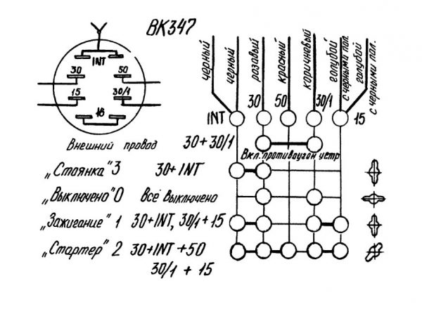
Table: list of switched circuits with different key positions in the ignition lock VAZ 2101
| Key position | live contact | Switched circuits |
| "Parking" | «30″-«INT» | Outdoor lighting, windshield wiper, heater |
| "30 / 1" | — | |
| "Turned off" | "30", "30/1" | — |
| "Ignition" | «30″-«INT» | — |
| "30/1"-"15" | Outdoor lighting, windshield wiper, heater | |
| "Starter" | “30″-“50” | Starter |
| “30″-“16” |
For operational control, the VAZ 2101 is equipped with instrumentation. Their reliable operation provides the driver with information about the condition of the vehicle.
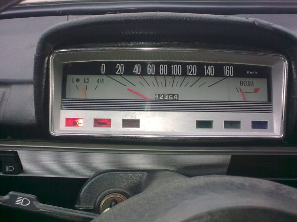
The instrument panel combination contains separate indicators with wide arrows, there are color zones on the scales to highlight border modes. Indicator readings withstand vibration while maintaining a stable position. The internal structure of the devices is insensitive to voltage changes.
Wiring diagram VAZ 2101 (injector)
The classic carburetor power system was widely used in Russian-made automotive circles. The simplicity of the carburetor systems and the minimum number of sensors provided affordable settings for different engine operating modes for any motorist. For example, the Solex model carburetor fully met the requirements of car owners during acceleration and stable movement. The lack of technical developments and expensive foreign parts for fuel injection systems for a long time did not allow the plant's specialists to switch to injection fuel supply. Therefore, the VAZ 2101 was not produced in a factory with an injector.
But, progress, and even more so foreign buyers, demanded the presence of an "injector". The electronic system eliminated the disadvantages of mechanical ignition control and carburetor fuel supply. Much later, models with electronic ignition and a single-point injection system from General Motors were produced for export with a 1,7-liter engine.
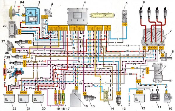
The position numbers of the electrical circuit elements in the diagram with single injection:
- Cooling fan.
- Mounting block.
- Idling regulator.
- Controller.
- Octane potentiometer.
- Spark plug.
- Ignition module.
- Crankshaft position sensor.
- Electric fuel pump with fuel level sensor.
- Tachometer.
- Control lamp CHECK ENGINE.
- Ignition relay.
- Speed sensor.
- Diagnostic box.
- Nozzle.
- Canister purge valve.
- Injection fuse.
- Injection fuse.
- Injection fuse.
- Injection ignition relay.
- Relay for turning on the electric fuel pump.
- Inlet pipe heater relay.
- Inlet pipe heater.
- Intake pipe heater fuse.
- Oxygen sensor.
- Coolant temperature sensor.
- Throttle position sensor.
- Air temperature sensor.
- Absolute pressure sensor.
Motorists who wish to independently equip a VAZ 2101 vehicle with an injection fuel supply system should understand the complexity of the work process and the need for material costs. To speed up the process of replacing a carburetor with an injector, it is worth purchasing a complete fuel injection kit for classic VAZ cars with all wiring, a controller, an adsorber and other parts. In order not to be wiser with the replacement of parts, it is better to purchase a cylinder head kit from the VAZ 21214 assembly.
Video: do-it-yourself injector on the VAZ 2101

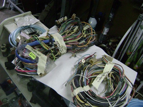
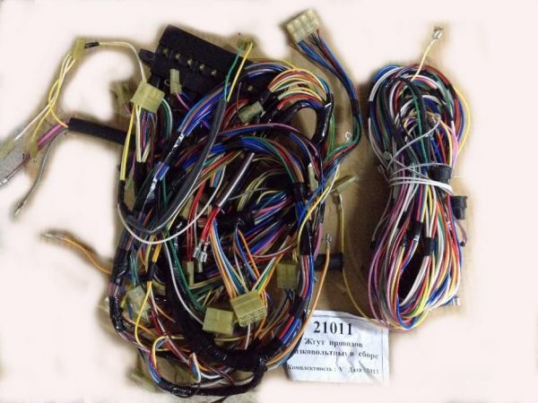
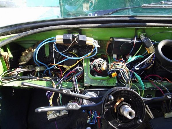
Underhood wiring
The electrical circuit of the iconic car is characterized by simple placement and reliable operation. The wires are connected to the appropriate sensors, devices and nodes. The tightness of the connection is ensured by convenient quick-disconnect plug-in connections.
The entire electrical wiring system can be divided into six bundles of wires:
- front;
- rear;
- right and left;
- beams of headlights and side indicators;
- battery wires;
- instrument panel wires.
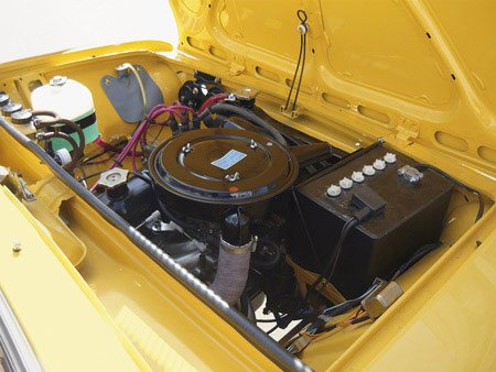
Under the hood wiring can include the front bundle of wires, wires for direction indicators and battery. The main sensors and instruments are located in the engine compartment:
- battery;
- starter;
- generator;
- ignition module;
- high voltage wires and spark plugs.
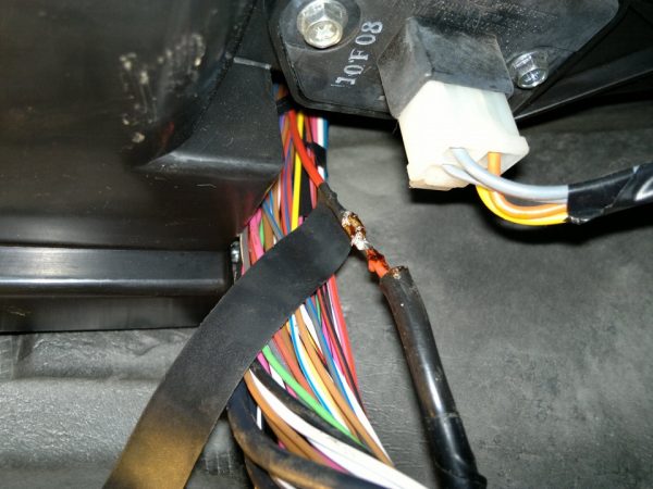
The thickest wires connecting the car body with the battery and the engine serve as the power supply for these devices. These wires carry the highest current when the engine is started. To protect electrical connections from water and dirt, the wires are equipped with rubber tips. To prevent scatter and tangling, all wires are bundled and divided into separate bundles, which are easier to replace if necessary.
The harness is wrapped with adhesive tape and fixed to the body, which prevents free hanging and trapping of individual wires by the moving parts of the power unit. At the location of a particular device or sensor, the bundle is divided into independent threads. Harnesses provide a certain order for connecting devices, which is reflected in the electrical circuit.
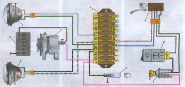
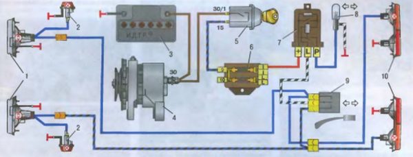
The position numbers of the electrical circuit elements on the VAZ 2101 headlight connection diagram:
- Lighthouse.
- Battery.
- Generator.
- Fuse box.
- Headlight switch.
- Switch.
- Egnition lock.
- High beam signaling device.
Latches on the plastic connector blocks ensure a secure connection, preventing accidental loss of contact from vibration.
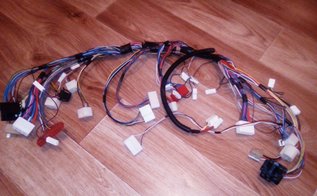
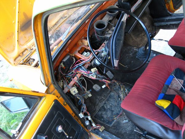
wiring harness in cabin
The front wiring harness, located in the engine compartment, is the main electrical supply system. The front beam passes into the car interior through a technological hole with a seal under the instrument panel. The front electrical system is connected to the instrument panel wires, fuse box, switches and ignition. In this part of the cabin, the main electrical circuits are protected by fuses.
The fuse box is located to the left of the steering wheel. Auxiliary relays are fixed behind the block on the bracket. The reliable operation of the VAZ 2101 depends on the proper functioning of electrical appliances and relays. Fuses protect the electrical circuits of the VAZ 2101 from short circuits.
List of electrical components protected by fuses:
- Sound signal, brake lights, ceiling lamps inside the cabin, cigarette lighter, portable lamp socket (16 A).
- Heating motor, wiper relay, windshield washer motor (8A).
- High beam left headlight, high beam warning lamp (8 A).
- High beam right headlight (8 A).
- Dipped beam of the left headlight (8 A).
- Dipped beam of the right headlight (8 A).
- Position light of the left sidelight, position light of the right rear lamp, indicator lamp of dimensions, instrument panel illumination lamp, license plate lamp, lamp inside the trunk (8 A).
- Position light of the right sidelight, position light of the left rear lamp, cigarette lighter lamp, engine compartment lamp (8 A).
- Coolant temperature sensor, fuel level sensor and reserve indicator lamp, oil pressure lamp, parking brake lamp and brake fluid level indicator, battery charge level lamp, direction indicators and their indicator lamp, reversing light, storage compartment lamp ("glove box" ) (8 A).
- Generator (excitation winding), voltage regulator (8 A).
It is not recommended to replace fuses with homemade jumpers. A foreign device may cause malfunction of electrical parts.
Video: replacing the old VAZ 2101 fuse box with a modern analogue

Switching of devices in the cabin is made with low-voltage wires with elastic oil- and petrol-resistant insulation. To facilitate troubleshooting, the wire insulation is made in different colors. For greater distinction, spiral and longitudinal strips are applied to the insulation surface in order to exclude the presence of two wires of the same color in the bundles..
On the steering column there are contacts for the switches for the direction indicator, low and high beams, and a sound signal. In the conditions of the assembly shop, the contacts of these switches are lubricated with a special conductive grease, which must not be removed during repairs. Lubrication reduces friction and prevents contact oxidation and possible sparking.
The position numbers of the electrical circuit elements on the direction indicator connection diagram:
- Sidelights.
- Side direction indicators.
- Battery.
- Generator.
- Egnition lock.
- Fuse box.
- Relay breaker.
- Switch-on signaling device.
- Switch.
- Rear lights.
The intermittent signal of the turn signals is determined by the relay-breaker. The ground connection is provided by black wires, the positive connections are pink or orange wires. In the passenger compartment, the wires are connected:
- instrument panel and indicator lights;
- beams of headlights;
- direction indicators;
- interior lighting;
- wiper;
- foot windshield washer.
On the left side of the cabin, under the floor mats, there is a rear wiring harness. A thread departs from it to the ceiling lamp switch in the door pillar and the parking brake lamp switch. The branch to the right ceiling passes behind the rear beam along the floor of the body, there are also wires connecting the level indicator sensor and the fuel reserve. The wires in the bundle are fixed with adhesive tape to the floor.
Replacing the wiring yourself
With numerous problems in the electrical system of the car, you should think about the complete replacement of the wiring, and not individual sections. When laying new wires, it is not recommended to combine low-voltage wires with high-voltage wires into one bundle. Reliable fastening to the case will exclude pinching of wires and damage of isolation. Appropriate plug sockets will ensure tight contact, which will eliminate the occurrence of breakdown and oxidation.
Replacing the wiring on their own is within the power of a motorist who has a superficial knowledge of an electrician.
Reasons for replacement
The amount of work depends on the degree of significance of the cause:
- failures in the operation of lighting devices;
- interruptions in the work of electronics;
- significant oxidation of contacts;
- frequent absence of current in the wires;
- battery discharge;
- numerous damage to the insulation of wires;
- many twists.
To replace part of the electrical wiring in the cabin, you must prepare:
- wiring diagram for electrical components;
- wires with different cross-sections and colored insulation;
- electrical tape;
- connecting blocks;
- terminals for wires;
- crimping pliers.
Replacement steps
Before starting work, you should sketch the location of the wires and the pinout of the pads.
Wiring replacement should be carried out in accordance with the safety rules and the electrical diagram:
- Disconnect the battery.
- Remove decorative plastic elements in the cabin.
- Determine the location of the required bundle of wires.
- Mark the wires to be replaced on the diagram.
- Disconnect the pads and carefully, without pulling, remove the old wires.
- Lay new wires.
- Connect pads.
- Make sure the wiring is in accordance with the diagram.
- Set decorative elements.
- Connect the battery.
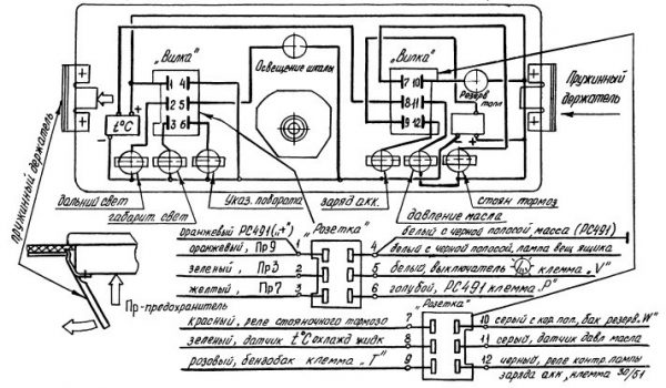
When replacing wiring on the instrument panel, follow the wiring diagram.
The position numbers of the elements of the electrical circuit on the diagram of control devices:
- Oil pressure warning light sensor.
- Coolant temperature gauge sensor.
- Level indicator and fuel reserve sensor.
- Fuel reserve control lamp.
- Parking brake and brake fluid level warning lamp.
- Oil pressure warning lamp.
- Fuel level indicator.
- A combination of devices.
- Coolant temperature gauge.
- Fuse box.
- The ignition switch.
- Generator.
- Accumulator battery.
- The relay-breaker of a control lamp of a parking brake.
- The switch of a control lamp of a parking brake.
- Brake fluid level sensor.
To avoid significant confusion in the wires and tedious detection of damage, it is worth considering purchasing a wiring harness kit for this model with all the blocks, plugs and connectors.
Video: wiring replacement and instrument panel installation from VAZ 2106

Electrical faults VAZ 2101
Statistical analysis of identified faults states that 40% of carburetor engine failures are due to the complex operation of the ignition system.
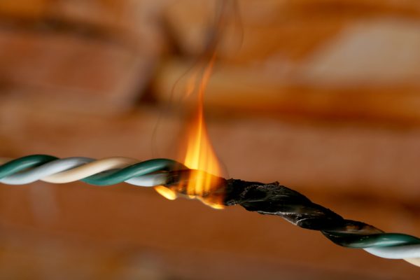
The failure of electrical equipment is determined visually, by the presence of voltage on the corresponding contacts: there is either current or it is not. Malfunctions cannot be determined in advance: by knocking, creaking or increased clearance. In the event of a malfunction, a short circuit is likely to occur in the wiring and electrical components. The appearance of a possible malfunction can be identified by heated wires and melted insulation.
The battery is a potential fire hazard. The location of the battery 6 ST-55P in the engine compartment of the VAZ 2101 is adjacent to the exhaust manifold, so it is possible to heat the battery bank with the “+” terminal, which will lead to the “boiling” of the electrolyte. Installing asbestos protection between the battery and the exhaust manifold will prevent the electrolyte from boiling away.
A motorist should understand that the work of electricity consumers depends on the reliable fastening of the generator and starter to the engine housing. The absence of one bolt or insufficient torque of the nut will lead to deformation of the shafts, jamming and breakage of the brushes.
Generator malfunction
Malfunctions in the operation of the generator are expressed in insufficient power of electric current. At the same time, the voltage drops and the control lamp lights up. If the alternator is damaged, the battery will be discharged. Burning of the collector and wear of the brushes are corrected by the driver independently by replacing the brushes and cleaning the collector with sandpaper. The short circuit of the stator windings cannot be repaired.
Table: possible generator malfunctions
| Malfunction | Cause of failure | elimination method |
| The control lamp does not light up |
|
|
| Lamp flashes intermittently |
|
|
| Insufficient battery charge |
|
|
| Increased noise during generator operation |
|
|
Procedure for checking a faulty generator
When the battery control lamp is on while the engine is running, elementary manipulations should be performed to check the generator:
- Open the hood.
- With one hand, increase the engine speed by pressing the throttle lever.
- With the other hand, remove the wire from the “-—” terminal of the battery for two seconds, after loosening the fastener.
- If the generator is not running, the engine will stall. This means that all consumers are battery powered.
If it is necessary to drive on a VAZ 2101 without a generator, remove fuse No. 10 and disconnect the black wire of the battery charge control lamp relay on the “30/51” plug. The ignition system will work when the voltage drops to 7 V. In this case, you should not use lighting, brakes and direction indicators. When the brake lights are turned on, the engine will stall.
With a faulty alternator, a normally charged battery allows you to drive up to 200 km.

The first VAZ 2101 models were equipped with an electromagnetic voltage regulator PP-380. Currently, this modification of the regulator has been discontinued; in case of replacement, modern analogues are installed. The regulator cannot be adjusted during operation. A voltmeter should be used to check its operation. A simple procedure will provide information about its compliance with the declared characteristics of the voltage correction in the on-board system:
- Start the engine.
- Switch off all current consumers.
- Measure the voltage at the battery terminals with a voltmeter.
- Normal operation of the regulator corresponds to a voltage of 14,2 V.
Starter malfunction
The starter provides the initial rotation of the crankshaft. The simplicity of its device does not negate the fact of importance in the operation of the overall system of the car. The product is subject to contamination and wear of parts. A large traction force is reflected in the condition of the fasteners and contact groups.
Table: probable starter malfunctions
| Malfunction | Cause of failure | elimination method |
| Starter does not work |
|
|
| The starter turns the engine slowly |
|
|
| Starter works, crankshaft does not rotate |
|
|
| Clicking sound when turned on |
|
|
Before removing the starter for replacement or repair, make sure that there are no secondary causes indicated in the table: battery discharge, oxidation of terminals and contacts, wire breakage.
Other faults
When the side electrodes in the cover of the ignition distributor burn out, they should be cleaned and the plates soldered to ensure an optimal gap between the electrode and the rotor contact. If a crack appears on the distributor housing from the central electrode to the side electrodes, it is worth filling the crack with epoxy glue.
A malfunction of the control lamps in the instrument panel and lighting lamps manifests itself not only when the filament burns out, but also in the absence of a reliable connection to ground. Cold lamp filaments have reduced resistance. At the moment of switching on, a large electric charge passes through the thread, instantly warming it up. Any shaking can lead to thread breakage due to reduced mechanical strength. Therefore, it is recommended to turn on the headlights when stationary.
Burning of contacts occurs for two reasons:
- Inappropriate parameters of the current flowing through the filaments of the lamps and through the contacts of the devices (voltage, current, resistance).
- Incorrect contact contact.
When working on the electrical equipment of the car, disconnect the wire from the negative terminal of the battery.
At the time of production, the VAZ 2101 car corresponded to the principles of comfort, reliability, manufacturability. Serious attention to the design development contributed to the reduction of maintenance costs during operation. From the driver's point of view, the model has decent efficiency and dynamics. The compact arrangement of parts and the presence of control devices facilitate operation and maintenance. The introduction of new technologies into the electrical circuit of the VAZ 2101 car is represented by a complex set of wires and electrical devices, the work of which is interconnected. The failure of one of the devices and the failure of the contact will lead to a malfunction of the entire system.

