Department: Brake Systems - Learn the secrets of sensors
 Patronage: ATE Continental. The wheel sensor system in modern braking systems, such as SBD ASR, EDS and ESP, is designed to transmit information about the number of wheel revolutions to the appropriate controller.
 Posted in Brake systems
Board of Trustees: ATE Continental
The more accurate the information that this system reports, the better and more comfortable the adjustment, which means the more perfect and more durable the braking system.
Passive (inductive) sensor
In the early years of ABS systems, it was enough for the wheel sensors to provide a signal from the moment a speed of approximately 7 km / h was reached. After the ABS was expanded with additional functions, such as: ASR, EDS and ESP, it became necessary that the design could transmit a full signal. Passive sensors were improved to be able to diagnose speeds as low as 3 km/h, but this was the limit of their capabilities.
Active sensor (magnetic resistance)
New-generation active sensors detect speed from 0 km/h for the first time. If we compare both sensor systems, we can see that the passive sensors have so far produced a sinusoidal signal. This signal was processed by the ABS controllers into a square wave, because only such signals allow the controllers to perform the necessary calculations. It is this task of the ABS controllers - converting a sinusoidal signal into a quadrilateral - that is transferred to the active wheel sensor. This means: the active sensor produces a four-way signal, which is directly used by the ABS control unit for the necessary calculations. The value of the sensor signal for pitch, wheel speed and vehicle speed remains unchanged.
Design and function of the passive sensor.
An inductive sensor consists of magnetic plates surrounded by a coil. Both ends of the coil are connected to  ABS controller. The ABS ring gear is located on the hub or driveshaft. As the wheel rotates, the magnetic field lines of the wheel sensor intersect through the ABS toothed ring, causing a sinusoidal voltage to be generated (induced) in the wheel sensor. Through constant changes: tooth-break, tooth-break, a frequency is generated, which is transmitted to the ABS controller. This frequency depends on the wheel speed.
Structure and functions of the active sensor
The magnetoresistive sensor consists of four replaceable resistors.
magnetically, a voltage source and a comparator (electrical amplifier). The principle of measurement through four resistors is known in physics as the Wheatstone bridge. This sensor system needs a decode wheel to work smoothly. The toothed ring of the sensor overlaps two resistors during movement, thereby detecting the measuring bridge and forming a sinusoidal signal. Reading electronics - the comparator converts the sinusoidal signal into a rectangular one. This signal can be directly used by the ABS controller for further calculations. The active sensor in vehicles with a decoding wheel consists of a sensor and a small reference magnet. The decoding wheel has an alternating polarity: the north and south poles alternate. The magnetized layer is coated with a rubber coating. The decoding wheel can also be built directly into the hub.
Reliable diagnostics
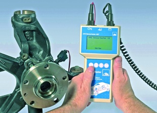
When troubleshooting modern brake control systems, specialists now need, in addition to diagnosing control units, the appropriate instruments to reliably test sensor systems. This task is performed by the new ATE AST tester from Continental Teves. It allows you to quickly and safely test passive and active wheel speed sensors. In active sensor systems, it is possible to control the impulse wheels without removing them. Using an extended set of cables, the ATE AST sensor can also test other ATE ESP sensors such as a vehicle turn sensor, a pressure sensor, and longitudinal and lateral acceleration sensors. If the supply voltage, the output signal and the pin assignment of the plug are known, it is even possible to analyze the sensors of other vehicle systems. Thanks to the ATE AST tester, time-consuming and costly diagnostics of sensors and other elements by their trial replacement is a
past.
Optimal processing system
The ATE AST Sensor Tester has a large, easy-to-read display with an option to turn on the backlight. The sensor is controlled by four foil buttons labeled in an intuitive way. It's a handy device
power supply from the car's onboard network Working with the ATE AST tester is completely intuitive. The menu is designed in such a way that the user goes through the entire diagnostic procedure step by step. So you do not have to study the instruction manual for a long time.
Automatic sensor recognition
When testing rotation speed sensors, the intelligent electronic system, after connecting and turning on the tester, automatically recognizes whether the sensor is passive or active, first or second generation. Further testing procedure depends on the type of sensor recognized. If the measured values deviate from the correct values, the user is provided with hints to find the error.
Investment in the future
Thanks to the flash memory, the software of the ATE AST sensor tester can be updated at any time via the PC interface. This makes it easy to make changes to the limit values. This practical tester is therefore a solid investment with which faults in the wheel speed sensors and the ESP system can be quickly and economically detected.
Basic rules for working with ABS magnetic wheel bearings:
• do not place the wheel bearing on a dirty work surface,
• Do not place a wheel bearing with a magnetic ring near a permanent magnet.
Note on removing the active wheel sensor:
• Do not insert sharp objects into the hole where the ABS sensor is installed, as this may damage the magnetic ring.
Wheel bearing installation note:
• note that the side with the magnetic ring faces the wheel sensor,
• mount bearings only in accordance with the recommendations of their manufacturer or vehicle manufacturer,
• never drive a bearing with a hammer,
• only press in bearings using the appropriate tools,
• Avoid damaging the magnetic ring.
