How to use a multimeter?
Content
Electricity and electronics are sciences built on the accurate measurement of all circuit parameters, the search for the relationship between them and the degree of influence on each other. Therefore, it is so important to be able to use universal measuring instruments - multimeters. They combine simpler specialized devices: ammeter, voltmeter, ohmmeter and others. By abbreviated names, they are sometimes called avometers, although the word "tester" is more common in the west. Let's figure out how to use a multimeter and what is it for?
Content
- 1 Purpose and functions
- 2 Multimeter device
- 3 Measurement of electrical parameters
- 3.1 Determination of current strength
- 3.2 Measuring voltage
- 3.3 How to measure resistance with a multimeter
- 4 Checking the elements of electrical circuits
- 4.1 Understanding Diodes and LEDs
- 4.2 Check the bipolar transistor
- 4.3 How to test a field effect transistor with a tester
- 4.4 How to test a capacitor with a multimeter
- 5 Wire continuity
- 6 How to use a multimeter in a car
Purpose and functions
The multimeter is designed to measure the three main parameters of an electrical circuit: voltage, current and resistance. To this basic set of functions, modes for checking the integrity of the conductor and the health of semiconductor devices are usually added. More complex and expensive devices are able to determine the capacitance of capacitors, the inductance of coils, the frequency of the signal, and even the temperature of the electronic component under study. According to the principle of operation, multimeters are divided into two groups:
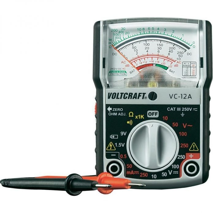
- Analog - an outdated type based on a magnetoelectric ammeter, supplemented with resistors and shunts for measuring voltage and resistance. Analog testers are relatively cheap, but tend to be inaccurate due to the low input impedance. Other disadvantages of the analog system include polarity sensitivity and a non-linear scale.

General view of the analog device
- Digital - more accurate and modern devices. In household models of the middle price segment, the permissible error does not exceed 1%, for professional models - a possible deviation lies within 0,1%. The "heart" of a digital multimeter is an electronic unit with logic chips, a signal counter, a decoder and a display driver. Information is displayed on a liquid crystal volatile screen.
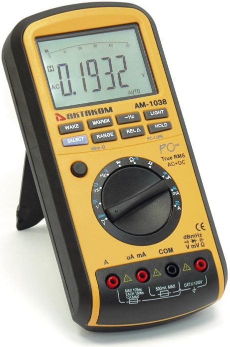
The error of household digital testers does not exceed 1%
Depending on the purpose and specifics of use, multimeters can be made in various form factors and use different current sources. The most widespread are:
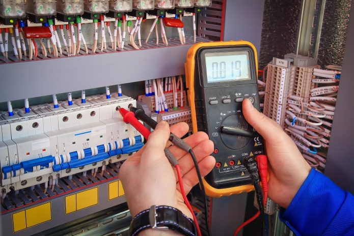
- Portable multimeters with probes are the most popular both in everyday life and in professional activities. They consist of a main unit equipped with batteries or an accumulator, to which flexible conductors-probes are connected. To measure a particular electrical indicator, the probes are connected to an electronic component or section of the circuit, and the result is read from the display of the device.
Portable multimeters are used in everyday life and industry: electronics, automation and during commissioning
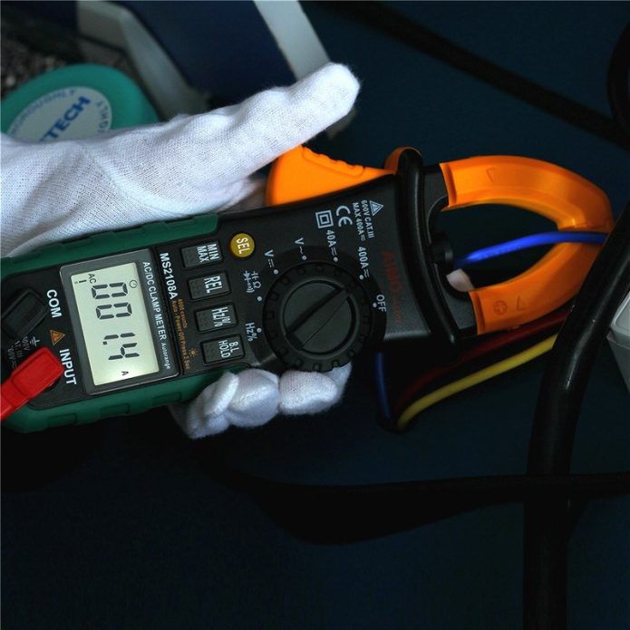
- Clamp meters - in such a device, the contact pads of the probes are interlocked on spring-loaded jaws. The user spreads them apart by pressing a special key, and then snaps into place on the section of the chain that needs to be measured. Often, clamp meters allow the connection of classic flexible probes.
Clamp meters allow you to measure electric current without breaking the circuit
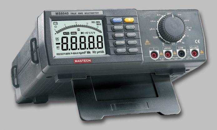
- Stationary multimeters are powered by a household alternating current source, they are distinguished by high accuracy and wide functionality, they can work with complex radio-electronic components. The main field of application is measurements in the development, prototyping, repair and maintenance of electronic devices.
Stationary or bench multimeters are most often used in electrical laboratories
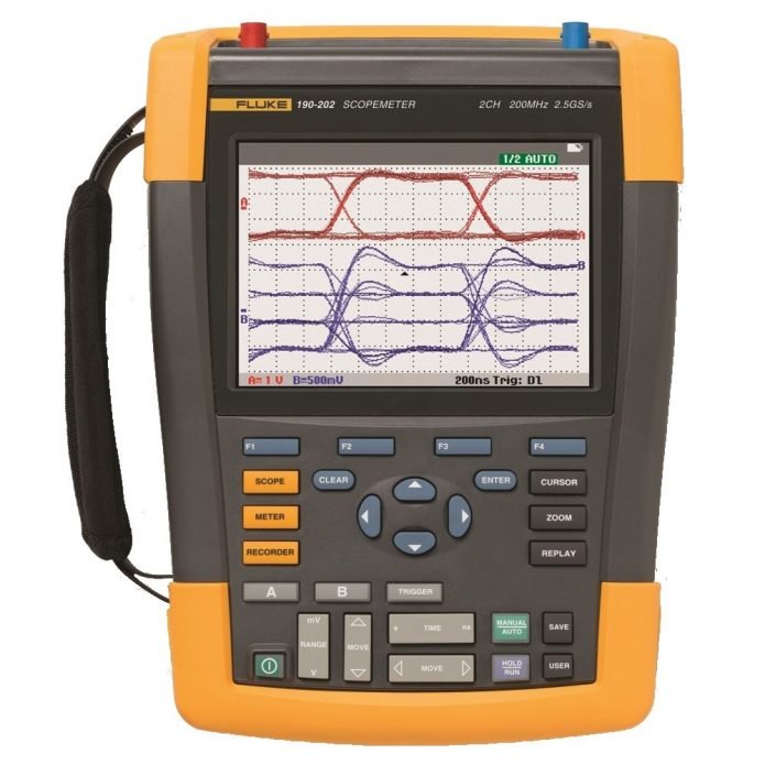
- Oscilloscopes-multimeters or scopmeters - combine two measuring instruments at once. They can be both portable and stationary. The price of such devices is very high, which makes them a purely professional engineering tool.
Scopmeters are the most professional equipment and are designed for troubleshooting in electric motor drives, power lines and transformers.
As you can see, the functions of a multimeter can vary within a fairly wide range and depend on the type, form factor, and price category of the device. So, a multimeter for home use should provide:
- Determining the integrity of the conductor;
- Search for "zero" and "phase" in the household electrical network;
- Measurement of alternating current voltage in a household electrical network;
- Measurement of voltage of low-power DC sources (batteries, accumulators);
- Determination of the basic indicators of the health of electronic devices - current strength, resistance.
Household use of a multimeter usually comes down to testing wires, checking the health of incandescent lamps, and determining the residual voltage in batteries.
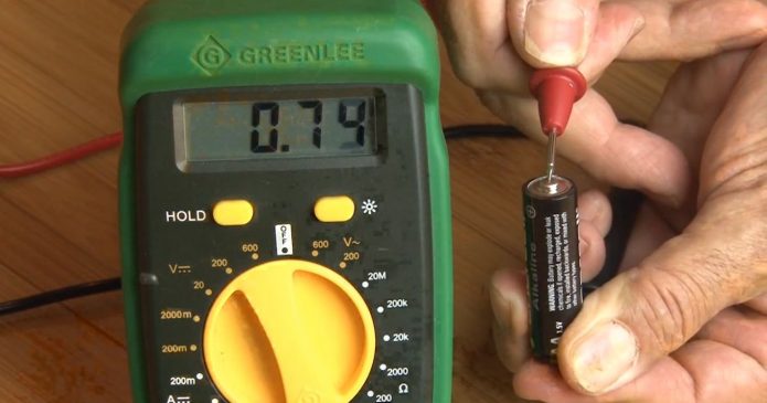
In everyday life, multimeters are used to test wires, check batteries and electrical circuits.
At the same time, the requirements for professional models are much stricter. They are determined separately for each particular case. Among the main features of advanced testers, it is worth noting:
- Possibility of comprehensive testing of diodes, transistors and other semiconductor devices;
- Determination of capacitance and internal resistance of capacitors;
- Determining the capacity of batteries;
- Measurement of specific characteristics - inductance, signal frequency, temperature;
- Ability to work with high voltage and current;
- High measurement accuracy;
- Reliability and durability of the device.
It is important to remember that a multimeter is a fairly complex electrical device, which should be handled competently and carefully.
Multimeter device
Most modern multimeters are equipped with detailed instructions that describe the sequence of actions for working with the device. If you have such a document - do not ignore it, get acquainted with all the nuances of the device model. We will talk about the main aspects of using any multimeter.
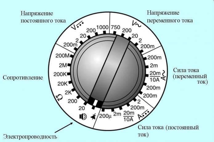
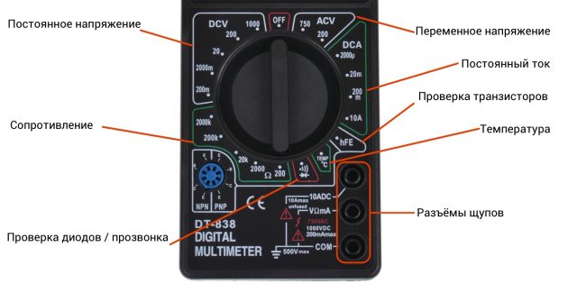
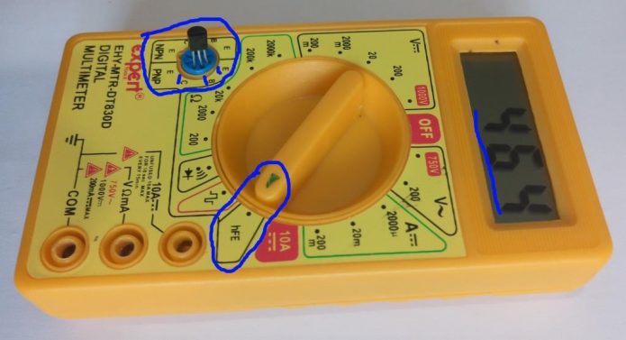
Standard switch switch includes: resistance, current and voltage measurements, as well as an electrical conductivity test
To select the operating mode, a switch is used, usually combined with a switch (“Off” position). For household appliances, it allows you to set the following maximum measurement limits:
- DC voltage: 0,2V; 2 V; 20 V; 200 V; 1000 V;
- AC voltage: 0,2V; 2 V; 20 V; 200 V; 750 V;
- DC current: 200 uA; 2 mA; 20 mA; 200 mA; 2 A (optional); 10 A (separate position);
- Alternating current (this mode is not available in all multimeters): 200 μA; 2 mA; 20 mA; 200 mA;
- Resistance: 20 ohm; 200 ohm; 2 kOhm; 20 kOhm; 200 kOhm; 2 MΩ; 20 or 200 MΩ (optional).
A separate provision serves to test the performance of the diodes and determine the integrity of the conductor. In addition, a transistor test socket is located to the side of the hard switch.
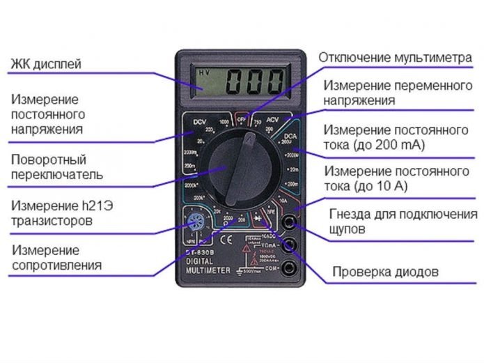
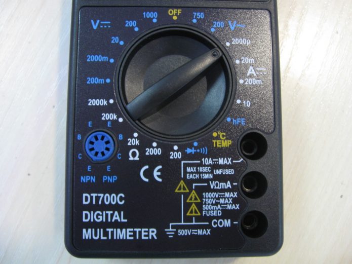
General switch layout of a budget multimeter
Using the device begins with setting the switch to the desired position. Then the probes are connected. There are two common stylus positions: vertical and horizontal.
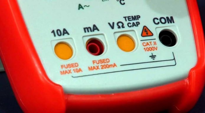
The connector marked with a ground icon and the inscription COM is negative or grounded - a black wire is connected to it; the connector, designated as VΩmA, is designed to measure resistance, voltage, and current, not exceeding 500 mA; connector labeled 10 A is designed to measure current in the range from 500 mA to the specified value
With a vertical arrangement, such as in the figure above, the probes are connected as follows:
- In the upper connector - a "positive" probe in the mode of measuring high current strength (up to 10 A);
- In the middle connector - a "positive" probe in all other modes;
- In the lower connector - the "negative" probe.
In this case, the current strength when using the second socket should not exceed 200 mA
If the connectors are located horizontally, carefully follow the symbols printed on the multimeter case. To the device shown in the figure, the probes are connected as follows:
- In the leftmost connector - the "positive" probe in the high current measurement mode (up to 10 A);
- In the second connector on the left - a "positive" probe in the standard measurement mode (up to 1 A);
- The third connector on the left is the “positive” probe in all other modes;
- In the connector on the far right is the “negative” probe.
The main thing here is to learn how to read the symbols and follow them. Remember that if the polarity is not observed or the measurement mode is incorrectly selected, you can not only get an incorrect result, but also damage the tester electronics.
Measurement of electrical parameters
There is a separate algorithm for each type of measurement. It is important to know how to use the tester, that is, to understand in which position to set the switch, to which sockets to connect the probes, how to turn on the device in an electrical circuit.
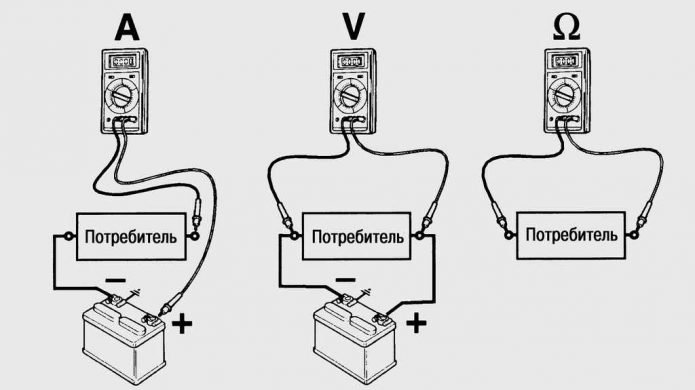
Tester connection diagram for measuring current, voltage and resistance
Determination of current strength
The value cannot be measured at the source, since it is characteristic of a section of the circuit or a certain consumer of electricity. Therefore, the multimeter is connected in series in the circuit. Roughly speaking, a measuring device replaces a part of the conductor in a closed source-consumer system.
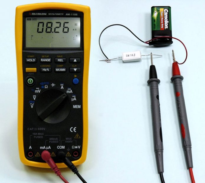
When measuring current, the multimeter must be connected in series in the circuit
From Ohm's law, we remember that the current strength can be obtained by dividing the source voltage by the consumer resistance. Therefore, if for some reason you cannot measure one parameter, then it can be easily calculated by knowing the other two.
Measuring voltage
Voltage is measured either at the current source or at the consumer. In the first case, it is enough to connect the positive probe of the multimeter to the “plus” of the power supply (“phase”), and the negative probe to the “minus” (“zero”). The multimeter will assume the role of the consumer and display the actual voltage.
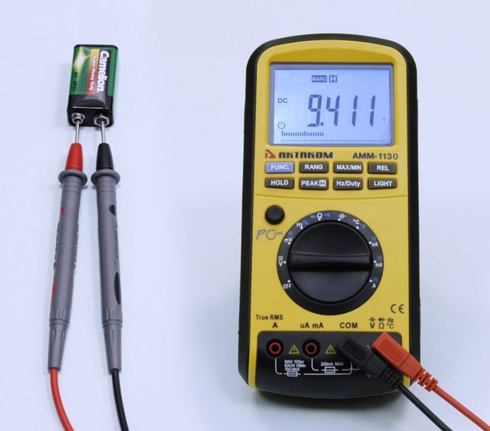
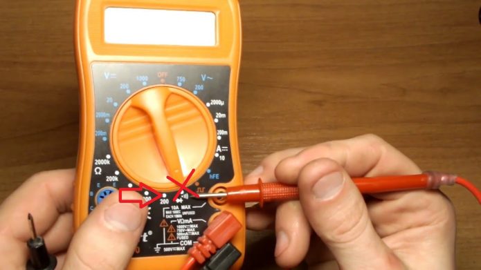
In order not to confuse the polarity, we connect the black probe to the COM jack and the minuses of the source, and the red probe to the VΩmA connector and plus
In the second case, the circuit is not opened, and the device is connected to the consumer in parallel. For analog multimeters, it is important to observe the polarity, digital in case of an error will simply show a negative voltage (for example, -1,5 V). And, of course, do not forget that voltage is the product of resistance and current.
How to measure resistance with a multimeter
The resistance of a conductor, sink or electronic component is measured with the power off. Otherwise, there is a high risk of damage to the device, and the measurement result will be incorrect.
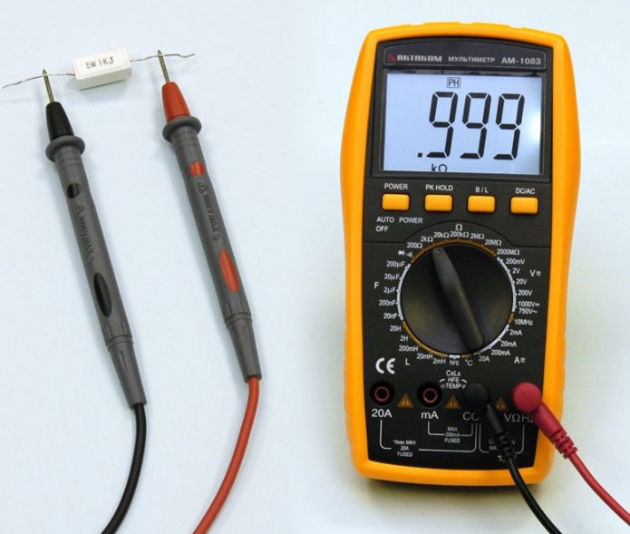
If the value of the measured resistance is known, then the measurement limit is chosen greater than the value, but as close as possible to it
To determine the value of the parameter, simply connect the probes to the opposite contacts of the element - polarity does not matter. Pay attention to the wide range of units of measurement - ohms, kiloohms, megaohms are used. If you set the switch to "2 MΩ" mode and try to measure a 10-ohm resistor, "0" will be displayed on the multimeter scale. We remind you that resistance can be obtained by dividing the voltage by the current.
Checking the elements of electrical circuits
Any more or less complex electronic device consists of a set of components, which are most often placed on a printed circuit board. Most breakdowns are caused precisely by the failure of these components, for example, thermal destruction of resistors, "breakdown" of semiconductor junctions, drying of the electrolyte in capacitors. In this case, the repair is reduced to finding the fault and replacing the part. This is where the multimeter comes in handy.
Understanding Diodes and LEDs
Diodes and LEDs are one of the simplest radio elements based on a semiconductor junction. The constructive difference between them is due only to the fact that the semiconductor crystal of the LED is capable of emitting light. The body of the LED is transparent or translucent, made of a colorless or colored compound. Ordinary diodes are enclosed in metal, plastic or glass cases, usually painted with opaque paint.
Semiconductor devices include varicaps, diodes, zener diodes, thyristors, transistors, thermistors and Hall sensors
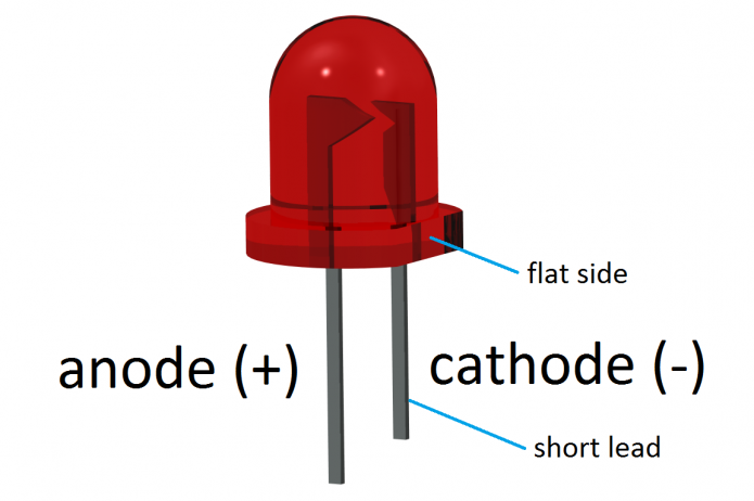
A characteristic feature of any diode is the ability to pass current in only one direction. The positive electrode of the part is called the anode, the negative one is called the cathode. Determining the polarity of the LED leads is simple - the anode leg is longer, and the inside is larger than that of the cathode. The polarity of a conventional diode will have to be searched on the Web. In circuit diagrams, the anode is indicated by a triangle, the cathode by a strip.
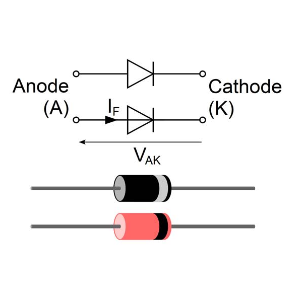
Image of a diode on a circuit diagram
To check a diode or LED with a multimeter, it is enough to set the switch to the “continuity” mode, connect the anode of the element to the positive probe of the device, and the cathode to the negative one. A current will flow through the diode, which will be displayed on the display of the multimeter. Then you should change the polarity and make sure that the current does not flow in the opposite direction, that is, the diode is not “broken”.
Check the bipolar transistor
A bipolar transistor is often represented as two connected diodes. It has three outputs: emitter (E), collector (K) and base (B). Depending on the type of conduction between them, there are transistors with "pnp" and "npn" structure. Of course, you need to check them in different ways.
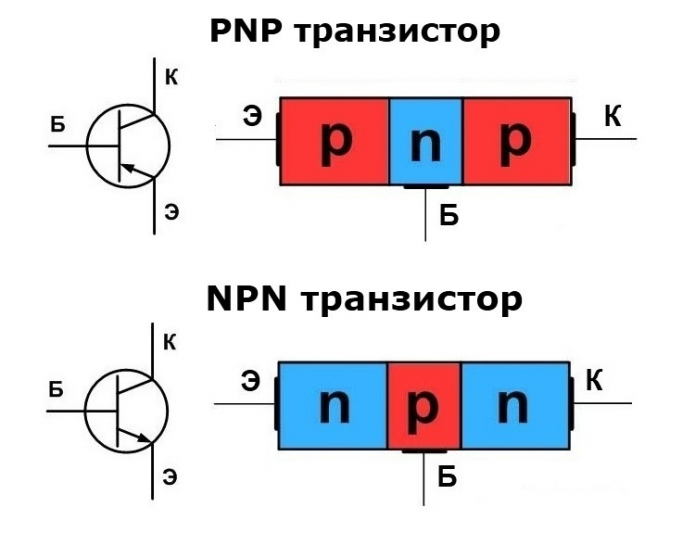
Image of emitter, base and collector regions on bipolar transistors
The sequence for checking a transistor with an npn structure:
- The positive probe of the multimeter is connected to the base of the transistor, the switch is set to the “ringing” mode.
- The negative probe touches the emitter and collector in series - in both cases, the device must record the passage of current.
- The positive probe is connected to the collector, and the negative probe to the emitter. If the transistor is good, the display of the multimeter will remain one, if not, the number will change and / or a beep will sound.
Transistors with a pnp structure are checked in a similar way:
- The negative probe of the multimeter is connected to the base of the transistor, the switch is set to the “ringing” mode.
- The positive probe touches the emitter and collector in series - in both cases, the device must record the passage of current.
- The negative probe is connected to the collector, and the positive probe to the emitter. Control the absence of current in this circuit.
The task will be greatly simplified if the multimeter has a probe for transistors. True, it should be borne in mind that powerful transistors cannot be checked in a probe - their conclusions simply will not fit in the sockets.
To test bipolar transistors on multimeters, a probe is most often provided
The probe is divided into two parts, each of which works with transistors of a certain structure. Install the transistor in the desired part, observing the polarity (base - in socket "B", emitter - "E", collector - "C"). Set the switch to position hFE - gain measurement. If the display remains one, the transistor is faulty. If the figure changes, the part is normal, and its gain corresponds to the specified value.
How to test a field effect transistor with a tester
Field-effect transistors are more complicated than bipolar transistors, since in them the signal is controlled by an electric field. Such transistors are divided into n-channel and p-channel, and their conclusions have received the following names:
- Prison (Z) - gate (G);
- East (I) - source (S);
- Drain (C) - drain (D).
You will not be able to use the probe built into the multimeter to test the field-effect transistor. We'll have to use a more complex method.
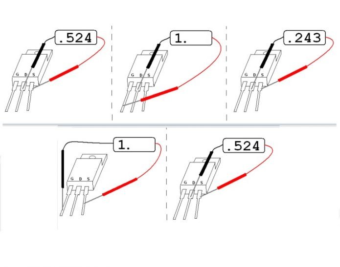
An example of checking the contacts of a field-effect transistor with a tester
Let's start with the n-channel transistor. First of all, they remove static electricity from it by alternately touching the terminals with a grounded resistor. Then the multimeter is set to the “ringing” mode and the following sequence of actions is performed:
- Connect the positive probe to the source, the negative probe to the drain. For most field-effect transistors, the voltage at this junction is 0,5-0,7 V.
- Connect the positive probe to the gate, the negative probe to the drain. One should remain on the display.
- Repeat the steps indicated in paragraph 1. You must fix the change in voltage (it is possible to both drop and increase).
- Connect the positive probe to the source, the negative probe to the gate. One should remain on the display.
- Repeat the steps in paragraph 1. The voltage should return to its original value (0,5-0,7 V).
Any deviation from the standard values indicates a malfunction of the field effect transistor. Parts with a p-channel transition are checked in the same sequence, changing the polarity to the opposite in each step.
How to test a capacitor with a multimeter
First of all, you should determine which capacitor you will be testing - polar or non-polar. All electrolytic and some solid-state capacitors are polar, and non-polar, as a rule, film or ceramic, have many times less capacitance (nano- and picofarads).
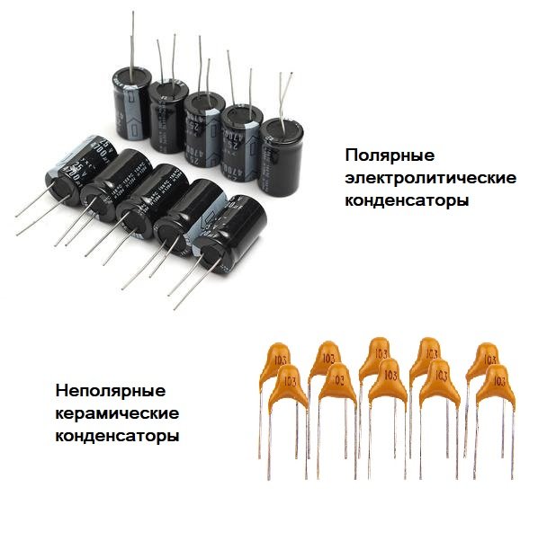
A capacitor is a two-terminal device with a constant or variable value of capacitance and low conductivity, and is used to accumulate the charge of an electric field.
If the capacitor has already been used (for example, soldered from an electronic device), then it must be discharged. Do not connect the contacts directly with a wire or a screwdriver - this will at best lead to breakage of the part, and at worst - to electric shock. Use an incandescent light bulb or a powerful resistor.
Capacitor testing can be divided into two types - the actual performance test and capacitance measurement. Any multimeter will cope with the first task, only professional and “advanced” household models will cope with the second.
The larger the value of the capacitor, the slower the value on the display changes.
To check the health of the part, set the multimeter switch to the “ringing” mode and connect the probes to the capacitor contacts (observing the polarity if necessary). You will see a number on the display, which will immediately begin to grow - this is the multimeter battery charging the capacitor.
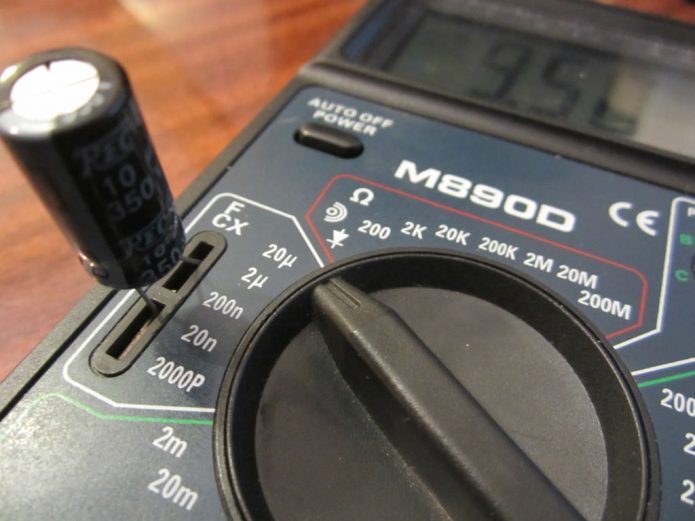
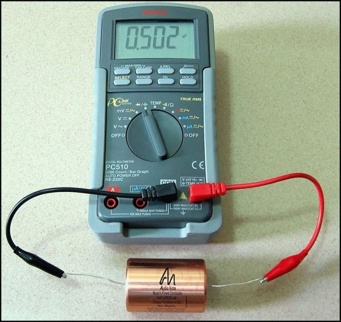
To check the capacitance of the capacitor, a special probe is used.
It is also not difficult to measure the capacitance with an “advanced” multimeter. Carefully inspect the capacitor case and find the capacitance designation in micro-, nano-, or picofarads. If instead of units of capacity a three-digit code is applied (for example, 222, 103, 154), use a special table to decipher it. After determining the nominal capacitance, set the switch to the appropriate position and insert the capacitor into the slots on the multimeter case. Check if the actual capacity matches the nominal capacity.
Wire continuity
Despite all the multitasking of multimeters, their main household use is the continuity of wires, that is, the determination of their integrity. It would seem that it could be simpler - I connected the two ends of the cable with the probes in the "tweeter" mode, and that's it. But this method will only indicate the presence of contact, but not the state of the conductor. If there is a tear inside, which leads to sparking and burning under load, then the piezo element of the multimeter will still make a sound. It is better to use the built-in ohmmeter.
An audible signal, otherwise referred to as a "buzzer", significantly speeds up the dialing process
Set the multimeter switch to the "one ohm" position and connect the probes to opposite ends of the conductor. The normal resistance of a stranded wire several meters long is 2-5 ohms. An increase in resistance to 10-20 ohms will indicate partial wear of the conductor, and values of 20-100 ohms indicate serious wire breaks.
Sometimes when checking a wire laid in a wall, using a multimeter is difficult. In such cases, it is advisable to use non-contact testers, but the price of these devices is quite high.
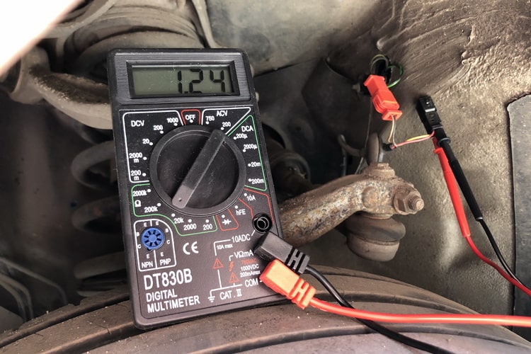
How to use a multimeter in a car
Electrical equipment is one of the most vulnerable parts of the car, which is very sensitive to operating conditions, timely diagnostics and maintenance. Therefore, the multimeter should become an integral part of the tool kit - it will help identify the malfunction, determine the causes of its occurrence and possible repair methods.
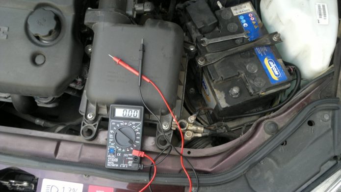
A multimeter is an indispensable device for diagnosing a vehicle's electrical system
For experienced motorists, specialized automotive multimeters are produced, but in most cases a household model will suffice. Among the main tasks that she has to solve:
- Monitoring the voltage on the battery, which is especially important after a long idle time of the car or in case of incorrect operation of the generator;
- Determination of the leakage current, search for short circuits;
- Checking the integrity of the windings of the ignition coil, starter, generator;
- Checking the diode bridge of the generator, components of the electronic ignition system;
- Monitoring the health of sensors and probes;
- Determining the integrity of the fuses;
- Checking incandescent lamps, toggle switches and buttons.
The problem that many motorists face is the discharge of the multimeter battery at the most inopportune moment. To avoid this, just turn off the device immediately after use and carry a spare battery with you.
A multimeter is a convenient and versatile device, indispensable both in everyday life and in professional human activities. Even with a basic level of knowledge and skills, it can significantly simplify the diagnosis and repair of electrical appliances. In skillful hands, the tester will help solve the most complex tasks - from signal frequency control to integrated circuit testing.
Discussions are closed for this page