How to check DBP
Content
If you suspect a breakdown of the absolute air pressure sensor in the manifold, motorists are interested in the question of whether how to check DBP with your own hands. This can be done in two ways - using a multimeter, as well as using software tools.
However, to perform a DBP check with a multimeter, you need to have the car's electrical circuit on hand in order to know which contacts to connect the multimeter probes to.
Symptoms of a broken DAD
With a complete or partial failure of the absolute pressure sensor (it is also called the MAP sensor, Manifold Absolute Pressure) outwardly, the breakdown manifests itself in the following situations:
- High fuel consumption. This is due to the fact that the sensor transmits incorrect data on the air pressure in the intake manifold to the computer, and, accordingly, the control unit issues a command to supply fuel in a larger quantity than necessary.
- Reducing the power of the internal combustion engine. This manifests itself in weak acceleration and insufficient traction when the car is moving uphill and / or in a loaded state.
- There is a persistent smell of gasoline in the throttle area. This is due to the fact that it is constantly overflowing.
- Unstable idle speed. Their value either drops or rises without pressing the accelerator pedal, and while driving, kicks are felt and the car twitches.
- "Failures" of the internal combustion engine in transient modes, namely, when shifting gears, starting the car from a place, regassing.
- Problems with starting the engine. Moreover, both "hot" and "cold".
- Formation in the memory of the electronic control unit errors with codes p0105, p0106, p0107, p0108 and p0109.
Most of the signs of failure described are general and can be caused by other causes. Therefore, you should always perform a comprehensive diagnosis, and you need to start, first of all, by scanning for errors in the computer.
How an absolute pressure sensor works
Before you check the absolute air pressure sensor, you need to understand its structure and principle of operation in general terms. This will facilitate the verification process itself and the accuracy of the result.
So, in the sensor housing there is a vacuum chamber with a strain gauge (a resistor that changes its electrical resistance depending on the deformation) and a membrane, which are connected via a bridge connection to the electrical circuit of the car (roughly speaking, to the electronic control unit, ECU). As a result of the operation of the internal combustion engine, the air pressure changes, which is fixed by the membrane and compared with vacuum (hence the name - the "absolute" pressure sensor). Information about the change in pressure is transmitted to the computer, on the basis of which the control unit decides on the amount of fuel supplied to form the optimal fuel-air mixture. The full cycle of the sensor is as follows:
- Under the influence of the pressure difference, the membrane is deformed.
- The specified deformation of the membrane is fixed by a strain gauge.
- With the help of a bridge connection, the variable resistance is converted into a variable voltage, which is transmitted to the electronic control unit.
- Based on the information received, the ECU adjusts the amount of fuel supplied to the injectors.
Modern absolute pressure sensors are connected to the computer using three wires - power, ground and signal wire. Accordingly, the essence of verification often boils down to the fact that in order to using a multimeter, check the value of resistance and voltage on the specified wires under various operating conditions of the internal combustion engine in general and the sensor namely. Some MAP sensors have four wires. In addition to these three wires, a fourth one is added to them, through which information about the air temperature in the intake manifold is transmitted.
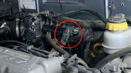
In most vehicles, the absolute pressure sensor is located precisely on the intake manifold fitting. On older vehicles, it may be located on flexible air lines and fixed to the vehicle body. In the case of tuning a turbocharged engine, DBP is often placed on the air ducts.
If the pressure in the intake manifold is low, then the signal voltage output by the sensor will also be low, and vice versa, as the pressure increases, the output voltage transmitted as a signal from the DBP to the ECU also increases. So, with a fully open damper, that is, at low pressure (approximately 20 kPa, different for different machines), the signal voltage value will be in the range of 1 ... 1,5 Volts. With the damper closed, that is, at high pressure (about 110 kPa and above), the corresponding voltage value will be 4,6 ... 4,8 Volts.
Checking the DBP sensor
Checking the absolute pressure sensor in the manifold comes down to the fact that you first need to make sure that it is clean, and, accordingly, the sensitivity to a change in air flow, and then find out its resistance and the output voltage during the operation of the internal combustion engine.
Cleaning the absolute pressure sensor
Please note that as a result of its operation, the absolute pressure sensor is gradually clogged with dirt, which blocks the normal operation of the membrane, which can cause a partial failure of the DBP. Therefore, before checking the sensor, it must be dismantled and cleaned.
To perform cleaning, the sensor must be dismantled from its seat. Depending on the make and model of the vehicle, the mounting methods and location will differ. Turbocharged ICEs usually have two absolute pressure sensors, one in the intake manifold, the other on the turbine. Usually the sensor is attached with one or two mounting bolts.
Cleaning of the sensor must be carried out carefully, using special carb cleaners or similar cleaners. In the process of cleaning, you need to clean its body, as well as contacts. In this case, it is important not to damage the sealing ring, the housing elements, the contacts and the membrane. You just need to sprinkle a small amount of cleaning agent inside and pour it back along with the dirt.
Very often, such a simple cleaning already restores the operation of the MAP sensor and there is no need to perform further manipulations. So after cleaning, you can put the air pressure sensor in place and check the operation of the internal combustion engine. If it did not help, then it is worth moving on to checking the DBP with a tester.
Checking the absolute pressure sensor with a multimeter
To check, find out from the repair manual which wire and contact is responsible for what in a particular sensor, that is, where are the power, ground and signal wires (signal in the case of a four-wire sensor).
in order to figure out how to check the absolute pressure sensor with a multimeter, you first need to make sure that the wiring between the computer and the sensor itself is intact and does not short anywhere, because the accuracy of the result will depend on this. This is also done using an electronic multimeter. With it, you need to check both the integrity of the wires for a break and the integrity of the insulation (determine the value of the insulation resistance on individual wires).
Consider the implementation of the corresponding check on the example of a Chevrolet Lacetti car. He has three wires suitable for the sensor - power, ground and signal. The signal wire goes straight to the electronic control unit. "Mass" is connected to the minuses of other sensors - the temperature sensor of the air entering the cylinders and the oxygen sensor. The supply wire is connected to the pressure sensor in the air conditioning system. Further check of the DBP sensor is performed according to the following algorithm:
- You need to disconnect the negative terminal from the battery.
- Disconnect the block from the electronic control unit. If we consider the Lacetti, then this car has it under the hood on the left side, near the battery.
- Remove the connector from the absolute pressure sensor.
- Set the electronic multimeter to measure electrical resistance with a range of approximately 200 ohms (depending on the specific model of the multimeter).
- Check the resistance value of the multimeter probes by simply connecting them together. The screen will show the value of their resistance, which will later need to be taken into account when performing a test (usually it is about 1 ohm).
- One multimeter probe must be connected to pin number 13 on the ECU block. The second probe is similarly connected to the first contact of the sensor block. this is how the ground wire is called. If the wire is intact and its insulation is not damaged, then the resistance value on the device screen will be approximately 1 ... 2 Ohm.
- next you need to pull the harnesses with wires. This is done in order to make sure that the wire is not damaged and changes its resistance while the car is moving. In this case, the readings on the multimeter should not change and be at the same level as in static.
- With one probe, connect to contact number 50 on the block block, and with the second probe, connect to the third contact on the sensor block. this is how the power wire “rings”, through which standard 5 volts are supplied to the sensor.
- If the wire is intact and not damaged, then the resistance value on the multimeter screen will also be approximately 1 ... 2 Ohm. Similarly, you need to pull the harness in order to prevent damage to the wire in the speaker.
- Connect one probe to pin number 75 on the ECU block, and the second to the signal contact, that is, contact number two on the sensor block (middle).
- Similarly, if the wire is not damaged, then the resistance of the wire should be about 1 ... 2 ohms. you also need to pull the harness with wires in order to make sure that the contact and insulation of the wires are reliable.
After checking the integrity of the wires and their insulation, you need to check whether the power comes to the sensor from the electronic control unit (supplying 5 Volts). To do this, you need to reconnect the computer block to the control unit (install it in its seat). After that, we put back the terminal on the battery and turn on the ignition without starting the internal combustion engine. With the probes of the multimeter, switched to the DC voltage measurement mode, we touch the sensor contacts - the supply and the "ground". If power is supplied, then the multimeter will display a value of about 4,8 ... 4,9 volts.
Similarly, the voltage between the signal wire and the "ground" is checked. Before that, you need to start the internal combustion engine. then you need to switch the probes to the corresponding contacts on the sensor. If the sensor is in order, then the multimeter will display information about the voltage on the signal wire in the range from 0,5 to 4,8 Volts. Low voltage corresponds to idle speed of the internal combustion engine, and high voltage corresponds to high speed of the internal combustion engine.
Syringe test
You can check the operation of the absolute pressure sensor using a medical disposable syringe with a volume of 20 “cubes”. also, for verification, you will need a sealed hose, which must be connected to the dismantled sensor and specifically to the syringe neck.
It is most convenient to use the ignition correction angle vacuum hose for VAZ vehicles with a carburetor ICE.
Accordingly, to check the DBP, you need to dismantle the absolute pressure sensor from its seat, but leave the chip connected to it. It is best to insert a metal clip into the contacts, and already connect the probes (or “crocodiles”) of the multimeter to them. The power test should be performed in the same way as described in the previous section. The power value should be within 4,8 ... 5,2 Volts.
To check the signal from the sensor, you need to turn on the car ignition, but do not start the internal combustion engine. At normal atmospheric pressure, the voltage value on the signal wire will be approximately 4,5 volts. In this case, the syringe must be in a “squeezed out” state, that is, its piston must be completely immersed in the body of the syringe. further, to check, you need to pull the piston out of the syringe. If the sensor is operational, then the voltage will decrease. Ideally, with a strong vacuum, the voltage value will drop to a value of 0,5 volts. If the voltage drops only to 1,5 ... 2 Volts and does not fall below, the sensor is faulty.
Please note that the absolute pressure sensor, although reliable devices, is quite fragile. They are non-repairable. Accordingly, if the sensor fails, it must be replaced with a new one.