How to check the knock sensor
Content
The question of how to check the knock sensor (hereinafter DD), worries many motorists, namely, those who have encountered DD errors. In fact, there are two basic methods of testing - mechanical and using a multimeter. The choice of one or another method depends, among other things, on the type of sensor; they are resonant and broadband. Accordingly, their verification algorithm will be different. For sensors, using a multimeter, measure the value of changing resistance or voltage. an additional check with an oscilloscope is also possible, which allows you to look in detail at the process of triggering the sensor.
The device and principle of operation of the knock sensor
Resonant knock sensor device
There are two types of knock sensors - resonant and broadband. Resonant ones are currently considered obsolete (they are commonly called “old ones”) and are not used in new cars. They have one output contact and are shaped like a barrel. The resonant sensor is tuned to a certain sound frequency, which corresponds to microexplosions in the internal combustion engine (fuel detonation). However, for each internal combustion engine, this frequency is different, since it depends on its design, piston diameter, and so on.
A broadband knock sensor, on the other hand, provides information about sounds to the internal combustion engine in the range from 6 Hz to 15 kHz (approximately, it may be different for different sensors). Namely, the ECU already decides whether a particular sound is a microexplosion or not. Such a sensor has two outputs and is most often installed on modern cars.
Two types of sensors
The basis of the design of a broadband knock sensor is a piezoelectric element, which converts the mechanical action imposed on it into an electric current with certain parameters (usually, the changing voltage supplied to the electronic control unit of the internal combustion engine, ECU is usually read). the so-called weighting agent is also included in the design of the sensor, which is necessary to increase the mechanical effect.
The broadband sensor has two output contacts, to which, in fact, the measured voltage is supplied from the piezoelectric element. The value of this voltage is supplied to the computer and, based on it, the control unit decides whether detonation occurs at this moment or not. Under certain conditions, a sensor error may occur, which the ECU informs the driver about by activating the Check Engine warning lamp on the dashboard. There are two basic methods for checking the knock sensor, and this can be done both with its dismantling and without removing the sensor from its installation site on the engine block.
Measuring voltage
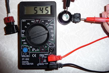
It is most effective to check the ICE knock sensor with a multimeter (another name is an electrical tester, it can be either electronic or mechanical). This check can be done by removing the sensor from the seat or by checking it right on the spot, however, it will be more convenient to work with dismantling. So, to check, you need to put the multimeter in the measurement mode of direct voltage (DC) in the range of approximately 200 mV (or less). After that, connect the probes of the device to the electrical terminals of the sensor. Try to make a good contact, as the quality of the test will depend on this, because some low-sensitivity (cheap) multimeters may not recognize a slight change in voltage!
then you need to take a screwdriver (or other strong cylindrical object) and insert it into the central hole of the sensor, and then act on the fracture so that a force arises in the inner metal ring (do not overdo it, the sensor housing is plastic and may crack!). In this case, you need to pay attention to the readings of the multimeter. Without mechanical action on the knock sensor, the voltage value from it will be zero. And as the force applied to it increases, the output voltage will also increase. For different sensors, it may be different, but usually the value is from zero to 20 ... 30 mV with a small or medium physical effort.
A similar procedure can be performed without dismantling the sensor from its seat. To do this, you need to disconnect its contacts (chip) and similarly connect the multimeter probes to them (also providing high-quality contact). then, with the help of any object, press on it or knock with a metal object near the place where it is installed. In this case, the voltage value on the multimeter should increase as the applied force increases. If during such a check the value of the output voltage does not change, most likely the sensor is out of order and must be replaced (these nodes cannot be repaired). However, it is worth making an additional check.
also, the value of the output voltage from the knock sensor can be checked by putting it on some metal surface (or another, but in order for it to conduct sound waves well, that is, detonate) and hit it with another metal object in close proximity with sensor (be careful not to damage the device!). A working sensor should respond to this by changing the output voltage, which will be directly displayed on the screen of the multimeter.
Similarly, you can check the resonant ("old") knock sensor. In general, the procedure is similar, you need to connect one probe to the output contact, and the second to its body (“ground”). After that, you need to hit the sensor body with a wrench or other heavy object. If the device is working, then the value of the output voltage on the screen of the multimeter will change for a short time. Otherwise, most likely, the sensor is out of order. However, it is worth checking its resistance additionally, since the voltage drop can be very small, and some multimeters may simply not catch it.
There are sensors that have output contacts (output chips). Checking them is carried out in a similar way, for this you need to measure the value of the output voltage between its two contacts. Depending on the design of a particular internal combustion engine, the sensor must be dismantled for this or can be checked right on the spot.
Please note that after the impact, the increased output voltage must necessarily return to its original value. Some faulty knock sensors, when triggered (hit on or near them), do increase the value of the output voltage, but the problem is that after exposure to them, the voltage remains high. The danger of this situation is that the ECU does not diagnose that the sensor is faulty and does not activate the Check Engine light. But in reality, in accordance with the information coming from the sensor, the control unit changes the ignition angle and the internal combustion engine can operate in a mode that is not optimal for the car, that is, with late ignition. This can manifest itself in increased fuel consumption, loss of dynamic performance, problems when starting the internal combustion engine (especially in cold weather) and other minor troubles. Such breakdowns can be caused by various reasons, and sometimes it is very difficult to understand that they are caused precisely by the incorrect operation of the knock sensor.
Resistance measurement
Knock sensors, both resonant and broadband, can be checked by measuring the change in internal resistance in a dynamic mode, that is, during their operation. The measurement procedure and conditions are completely similar to the voltage measurement described above.
The only difference is that the multimeter is switched on not in the voltage measurement mode, but in the electrical resistance value measurement mode. The measurement range is up to approximately 1000 ohms (1 kOhm). In a calm (non-detonation) state, the electrical resistance values will be approximately 400 ... 500 Ohms (the exact value will differ for all sensors, even those that are identical in model). Measurement of wideband sensors must be performed by connecting the multimeter probes to the sensor leads. then knock either on the sensor itself or in close proximity to it (at the place of its attachment in the internal combustion engine, or, if it is dismantled, then put it on a metal surface and hit it). At the same time, carefully monitor the readings of the tester. At the moment of knocking, the resistance value will briefly increase and return back. Typically, the resistance increases to 1 ... 2 kOhm.
As in the case of measuring voltage, you need to make sure that the resistance value returns to its original value, and does not freeze. If this does not happen and the resistance remains high, then the knock sensor is faulty and should be replaced.
As for the old resonant knock sensors, the measurement of their resistance is similar. One probe must be connected to the output terminal, and the other to the input mount. Be sure to provide quality contact! then, using a wrench or a small hammer, you need to lightly hit the sensor body (its “barrel”) and in parallel look at the tester readings. They should increase and return to their original values.
It is worth noting that some auto mechanics consider measuring the resistance value to be a higher priority than measuring the voltage value when diagnosing a knock sensor. As mentioned above, the voltage change during the operation of the sensor is very small and amounts to literally a few millivolts, while the change in the resistance value is measured in whole ohms. Accordingly, not every multimeter is able to record such a small voltage drop, but almost any change in resistance. But, by and large, it does not matter and you can perform two tests in series.
Checking the knock sensor on the electrical block
There is also one method for checking the knock sensor without removing it from its seat. To do this, you need to use the ECU plug. However, the complexity of this check is that you need to know which sockets in the block correspond to the sensor, because each car model has an individual electrical circuit. Therefore, this information (pin and / or pad number) needs to be further clarified in the manual or on specialized resources on the Internet.
You need to connect to known pins on the block
The essence of the test is to measure the value of the signals supplied by the sensor, as well as to check the integrity of the electrical / signal circuit to the control unit. To do this, first of all, you need to remove the block from the engine control unit. On the block you need to find two desired contacts to which you need to connect the multimeter probes (if the probes do not fit, then you can use the "extension cords" in the form of flexible wires, the main thing is to ensure a good and strong contact). On the device itself, you need to enable the mode for measuring direct voltage with a limit of 200 mV. then, similarly to the method described above, you need to knock somewhere in the vicinity of the sensor. In this case, on the screen of the measuring device, it will be possible to see that the value of the output voltage changes abruptly. An additional advantage of using this method is that if a change in voltage is detected, then the wiring from the ECU to the sensor is guaranteed to be intact (no breakage or damage to the insulation), and the contacts are in order.
it is also worth checking the condition of the shielding braid of the signal / power wire coming from the computer to the knock sensor. The fact is that over time or under mechanical influence, it can be damaged, and its effectiveness, accordingly, will decrease. Therefore, harmonics may appear in the wires, which are not produced by the sensor, but appear under the influence of extraneous electric and magnetic fields. And this can lead to the adoption of false decisions by the control unit, respectively, the internal combustion engine will not work in the optimal mode.
Please note that the methods described above with voltage and resistance measurements only show that the sensor is operational. However, in some cases, it is not the presence of these jumps that is important, but their additional parameters.
How to identify a breakdown using a diagnostic scanner
In a situation where symptoms of a knock sensor failure are observed and the internal combustion engine light is on, it is a little easier to find out exactly what the reason is, it is enough to read the error code. If there are problems in its power circuit, error P0325 is fixed, and if the signal wire is damaged, P0332. If the sensor wires are shorted or its fastening is poor, other codes can be set. And in order to find out, it’s enough to have an ordinary, even a Chinese diagnostic scanner with an 8-bit chip and compatibility with a car (which may not always be the case).
When there is detonation, a decrease in power, unstable operation during acceleration, then it is possible to determine whether such problems really arose due to a breakdown of the DD only with the help of an OBD-II scanner that is able to read the performance of system sensors in real time. A good option for such a task is Scan Tool Pro Black Edition.
When checking the operation of the knock sensor with a scanner, you need to look at indicators regarding misfires, injection duration, engine speed, its temperature, sensor voltage and ignition timing. By comparing these data with those that should be on a serviceable car, it is possible to make a conclusion whether the ECU changes the angle and set it late for all ICE operating modes. UOZ varies depending on the mode of operation, the fuel used, the internal combustion engine of the car, but the main criterion is that it should not have sharp jumps.
UOS at idle
UOZ at 2000 rpm
Checking the knock sensor with an oscilloscope
There is also one method for checking DD - using an oscilloscope. In this case, it is unlikely that it will be possible to check the performance without dismantling, since usually an oscilloscope is a stationary device and it is not always worth carrying it to the garage. On the contrary, removing the knock sensor from the internal combustion engine is not very difficult and takes several minutes.
The check in this case is similar to those described above. To do this, you need to connect two oscilloscope probes to the corresponding sensor outputs (it is more convenient to check a broadband, two-output sensor). further, after selecting the operating mode of the oscilloscope, you can use it to look at the shape of the amplitude of the signal coming from the diagnosed sensor. In quiet mode, it will be a straight line. But if mechanical shocks are applied to the sensor (not very strong, in order not to damage it), then instead of a straight line, the device will show bursts. And the stronger the blow, the greater the amplitude.
Naturally, if the amplitude of the signal does not change during the impact, then most likely the sensor is out of order. However, it is better to diagnose it additionally by measuring the output voltage and resistance. also remember that the amplitude spike should be short-term, after which the amplitude is reduced to zero (there will be a straight line on the oscilloscope screen).
You need to pay attention to the shape of the signal from the sensor
However, even if the knock sensor worked and gave out some kind of signal, then on the oscilloscope you need to carefully study its shape. Ideally, it should be in the form of a thick needle with one sharp, pronounced end, and the front (sides) of the splash should be smooth, without notches. If the picture is like this, then the sensor is in perfect order. If the pulse has several peaks, and its fronts have notches, then it is better to replace such a sensor. The fact is that, most likely, the piezoelectric element has already become very old in it and it produces an incorrect signal. After all, this sensitive part of the sensor gradually fails over time and under the influence of vibration and high temperatures.
Thus, the diagnosis of a knock sensor with an oscilloscope is the most reliable and complete, giving the most detailed picture of the technical condition of the device.
How can you check DD
There is also one, fairly simple, method for checking the knock sensor. It lies in the fact that when the internal combustion engine is idling at a speed of approximately 2000 rpm or a little higher, using a wrench or a small hammer, they strike somewhere in the immediate vicinity of the sensor (however, it is not worth hitting directly on the cylinder block, so as not to damage it). The sensor perceives this impact as a detonation and transmits the corresponding information to the ECU. The control unit, in turn, reduces the speed of the internal combustion engine, which can be easily heard by ear. However, remember that this verification method does not always work! Accordingly, if in such a situation the speed has decreased, then the sensor is in order and further verification can be omitted. But if the speed remains at the same level, you need to conduct additional diagnostics using one of the above methods.
On some vehicles, the knock sensor algorithm is associated with information about the position of the crankshaft. That is, DD does not work constantly, but only when the crankshaft is in a certain position. Sometimes this principle of operation leads to problems in diagnosing the state of the sensor. This is one of the reasons RPMs won't drop at idle just because the sensor has been hit or near it. In addition, the ECU makes a decision about the detonation that has occurred, not only based on information from the sensor, but also taking into account additional external factors, such as the temperature of the internal combustion engine, its speed, vehicle speed, and some others. All this is embedded in the programs by which the ECU works.
In such cases, you can check the knock sensor as follows ... For this, you need a stroboscope, in order to use it on a running engine to achieve the “standing” position of the timing belt. It is in this position that the sensor is triggered. then with a wrench or a hammer (for convenience and in order not to damage the sensor, you can use a wooden stick) to apply a slight blow to the sensor. If the DD is working, the belt will twitch a little. If this did not happen, the sensor is most likely faulty, additional diagnostics must be performed (measurement of voltage and resistance, the presence of a short circuit).
also in some modern cars there is a so-called "rough road sensor", which works in tandem with a knock sensor and, under the condition that the car shakes strongly, it makes it possible to exclude false positives of DD. That is, with certain signals from the rough road sensor, the ICE control unit ignores the responses from the knock sensor according to a certain algorithm.
In addition to the piezoelectric element, there is a resistor in the knock sensor housing. In some cases, it may fail (burn out, for example, from high temperature or poor soldering at the factory). The electronic control unit will perceive this as a wire break or short circuit in the circuit. Theoretically, this situation can be corrected by soldering a resistor with similar technical characteristics near the computer. One contact must be soldered to the signal core, and the second to the ground. However, the problem in this case is that the resistance values of the resistor are not always known, and soldering is not very convenient, if not impossible. Therefore, the easiest way is to buy a new sensor and install it instead of a failed device. also by soldering additional resistance, you can change the sensor readings and install an analogue from another car instead of the device recommended by the manufacturer. However, as practice shows, it is better not to engage in such amateur performances!
Final result
Finally, a few words about installing the sensor after checking it. Remember that the metal surface of the sensor must be clean and free of debris and/or rust. Clean this surface before installation. Similarly with the surface on the seat of the sensor on the body of the internal combustion engine. it also needs to be cleaned. The sensor contacts can also be lubricated with WD-40 or its equivalent for preventive purposes. And instead of the traditional bolt with which the sensor is attached to the engine block, it is better to use a more reliable stud. It secures the sensor more tightly, does not weaken the fastening and does not unwind over time under the influence of vibration.