How to check valve clearance adjustment
Content
- Part 1 of 7. Learn Your System
- Part 2 of 7: Determine if your car needs a valve adjustment
- Part 3 of 7: Removing the valve cover or covers
- Part 4 of 7. Determine the type of valve adjustment system in your vehicle.
- Part 5 of 7: Checking and/or Adjusting Non-Hydraulic Type Valves
- Part 6 of 7: Hydraulic lift adjustment
- Part 7 of 7: Toyota Solid Pushrod Adjustment
The term "valve adjustment" is an oxymoron. What is actually adjustable is the clearance between the camshaft linkage and the valve. It is most commonly referred to as valve clearance. This system, which links the camshaft to…
The term "valve adjustment" is an oxymoron. What is actually adjustable is the clearance between the camshaft linkage and the valve. It is most commonly referred to as valve clearance. This system, which links the camshaft to the valve, has many designs. All require adjustment upon first assembly, but some require little to no maintenance after initial adjustment. Each system has its own strengths and weaknesses in both performance and maintenance cycles. This article will help you check the valve and adjust the valve clearance if necessary.
Part 1 of 7. Learn Your System
- Attention: The list of tools below is a complete list for adjusting any type of valve system. Refer to Part 3, Step 2 for the specific tool required for the type of valve system you will be working on.
Part 2 of 7: Determine if your car needs a valve adjustment
Required material
- Stethoscope
Step 1: Listen for valve noise. The need to adjust the valves is determined by their sound.
More precisely, the louder the knock in the valve mechanism, the greater the need for adjustment. A properly adjusted valve clearance will be quiet. Some systems will always make a slight knock, but it should never be loud enough to overshadow all other engine noises.
- AttentionA: Knowing when valves are too loud depends on experience. Not to mention that they get louder very gradually and we often don't notice this fact. If you're unsure, find someone with experience to help you determine if an adjustment is needed.
Step 2: Determine where the noise is coming from. If you have determined that your valves need adjustment, you can either adjust all of them or only adjust the ones that need it.
Dual head engines like V6 or V8 will have two sets of valves. Use a stethoscope and take some time to pinpoint the problematic valve by identifying the loudest one.
Part 3 of 7: Removing the valve cover or covers
Necessary materials
- Ratchet and rosette
- Screwdriver
Step 1: Remove all components mounted above or on the valve cover or covers.. It could be wiring harnesses, hoses, pipes, or an intake manifold.
You don't need to completely remove it all from the car. You just need to make room to remove the valve cover from the head and gain access to the valve adjusters.
Step 2: Remove the valve cover bolts or nuts.. Turn the bolts or nuts counterclockwise to remove them.
Make sure you remove them all. They often hide in unsuspecting places.
Functions: There is often an accumulation of oil-caked dirt that hides the valve cover bolts or nuts. Be sure to remove these deposits to carefully inspect the valve cover for what is holding it.
Functions: The valve cover bolts and nuts are usually attached at the outer edge, but often several nuts or bolts are attached in the middle of the valve cover. Be sure to carefully inspect them all.
Step 3: Gently but firmly pry the valve cover off the head.. Often the valve cover is glued to the head and additional force will be required to remove it.
This will require you to find a safe, strong area to pry off the valve cover. You can use a flathead screwdriver, insert it between the valve cover and the head, and carefully pry it out, or you can use a pry bar as a lever and do the same from somewhere else.
- A warning: Be careful not to break the valve cover. Do not use excessive force. Prolonged, gentle prying in several places is often required before the valve cover gives way. If you feel like you're trying to peep too hard, you probably are.
Part 4 of 7. Determine the type of valve adjustment system in your vehicle.
Step 1. Determine what type of valve clearance adjuster your vehicle has.. If you are unsure after reading the following descriptions, you should refer to the appropriate repair manual.
The hydraulic self-adjusting valve clearance system is hydraulic and only requires the setting of an initial preload. Self-adjustment is achieved through the use of a hydraulic lift that is charged by the engine's oil pressure system.
The term "solid pushrod" is often used to describe a non-hydraulic lifter, but it mostly refers to a non-hydraulic valve train. A solid pusher design may or may not use lifters. Some have rocker arms while others use cam followers. Non-hydraulic valve trains require regular adjustment to maintain proper valve clearance.
The cam follower simply rides straight on the camshaft cam; he follows the camera. It can be in the form of a rocker arm or a lift. The differences between a lifter and a cam follower are often semantic.
The Toyota cam follower with washer is very effective until adjustment is required. Adjustment of the cam follower in the form of a washer requires the replacement of gaskets installed in the cam follower, which is a laborious process.
Accurate measurements are required and it usually takes several steps of disassembly and reassembly to get everything right. Washers or spacers are purchased individually or as a kit from Toyota and can be quite expensive. For this reason, many people will neglect this style of valve adjustment.
Step 2. Determine what tools you need to set up your particular system.. Anything but the hydraulic system will require a dipstick.
A hydraulic lift system will require the correct size socket and ratchet.
A solid pusher will require feeler gauges, the correct size wrench, and a flat head screwdriver. Cam followers require the same as a solid follower. Basically, they are the same systems.
Toyota washer-type solid tappets require feeler gauges, a micrometer, and tools to remove the camshaft and timing belt or chain. Refer to repair manual for instructions on removing camshaft, timing belt or timing chain.
Part 5 of 7: Checking and/or Adjusting Non-Hydraulic Type Valves
Necessary materials
- Ring wrench of correct size
- Thickness gauges
- micrometer
Remote starter switch
Note: Part 5 applies to both cam followers and solid followers.
Step 1: Connect Remote Starter Switch. First connect the remote starter switch to the smaller wire on the starter solenoid.
If you are not sure which wire is the exciter wire, you will need to refer to the wiring diagram in your repair manual to be sure. Connect the other wire from the remote starter switch to the positive battery post.
If your starter exciter wire is not available, you will need to crank the engine by hand using a ratchet or wrench on the crankshaft bolt. Many vehicles have a remote solenoid on the fender to which a remote starter switch can be connected.
It will always be easier to use a remote switch, but you will need to evaluate the effort it takes to connect it versus the effort it takes to crank the motor by hand.
Step 2: Find the correct valve clearance in the instruction manual.. Often this specification can be found under the hood of your car on an emissions sticker or other decal.
There will be an exhaust and intake specification.
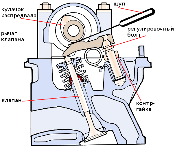
Step 3: Set the first set of valves to the closed position.. Position the camshaft lobes that are in contact with the rocker arm or cam followers directly opposite the cam nose.
Attention: It is essential that the valves are in the closed position when adjusting the valves. They cannot be adjusted in any other position.
Functions: The most accurate way to check valve clearance is to check it at three locations on the underside of the cam lobe. It is called the base circle of the cam. You want to check this space with a feeler gauge in the center of the base circle and on each side of it before it starts to rise towards the nose. Some vehicles are more sensitive to this adjustment than others. Often you can just test it at the center of the base circle, but some motors are best tested at the three points above.
Step 4: Insert the correct probe. This will either happen on the camshaft cam or on top of that valve.
Taking this measurement on the camshaft will always be the most accurate, but it is often not possible to access the camshaft lug.
Step 5: Move the feeler gauge in and out to feel how tight the adjustment is.. The probe should not slide too easily, but should not be too tight to make it difficult to move.
If it is too tight or too loose, you will need to loosen the locknut and turn the adjuster in the correct direction to tighten or loosen it.
Step 6: Tighten the lock nut. Be sure to hold the regulator with a screwdriver.
Step 7: Check the gap again with a feeler gauge.. Do this after tightening the lock nut.
Often the adjuster will move when the locknut is tightened. If so, repeat steps 4-7 again until the clearance appears correct with a feeler gauge.
- Functions: The probe should feel firm, but not tight. If it easily falls out of the gap, it is too loose. The more precisely you do this, the quieter the valves will run when you're done. Spend more time on the first few valves to appreciate the feel of a properly adjusted valve. Once you get it, you can go through the rest faster. Every car will be slightly different, so don't expect them all to be the same.
Step 8: Move the camshaft to the next valve.. This may be the next in the firing order or the next row on the camshaft.
Determine which method is the most time efficient and follow this pattern for the rest of the valves.
Step 9: Repeat steps 3-8. Do this until all valves are adjusted to the correct clearance.
Step 10: Install the valve covers. Be sure to install any other components you may have removed.
Part 6 of 7: Hydraulic lift adjustment
Necessary materials
- Ring wrench of correct size
- Thickness gauges
- micrometer
- Remote starter switch
Step 1: Determine the correct lifter preload for the engine you are working on.. You will need to refer to the repair manual for your year and model for this specification.
Step 2: Set the first valve to the closed position.. To do this, use a remote starter or crank the engine by hand.
Step 3: Turn the adjusting nut clockwise until you reach zero clearance.. Refer to the above definitions for zero strike.
Step 4: Turn the nut the additional amount specified by the manufacturer.. It can be as little as a quarter of a turn or as many as two turns.
The most common preload is one turn or 360 degrees.
Step 5: Use the remote start switch to move the next valve to the closed position.. You can follow the ignition order or follow each valve as it is located on the camshaft.
Step 6: Install the valve cover. Be sure to install any other components you may have removed.
Part 7 of 7: Toyota Solid Pushrod Adjustment
Required material
- Ring wrench of correct size
Step 1: Determine the correct valve clearance. The valve clearance range for intake and exhaust valves will be different.
Step 2: Measure the valve clearance of each valve before disassembly.. Be especially careful when making this measurement.
It should be as accurate as possible and measured in the same way as the solid tappets described above.
Step 3: Subtract the amount given by the manufacturer from the actual measured amount.. Note which valve it is for and record the difference.
You will add the difference to the size of the original lifter if the clearance is not within specification.
Step 4: Remove the camshaft from the head. Do this if you find that some valves do not meet the manufacturer's specifications.
To do this, you will need to remove the timing belt or timing chain. Refer to the appropriate repair manual for instructions during this part of the procedure.
Step 5Tag All Camera Followers By Location. Specify cylinder number, inlet or outlet valve.
Step 6: Remove the cam followers from the head.. Earlier designs have a separate washer that can be removed from the pushrod or lifter as some call it.
Newer designs require the lift itself to be measured and replaced if it is out of specification.
Step 7: Measure the thickness of the lifter or inserted washer. If the valve clearance is not within specification, add the difference between the actual clearance and the manufacturer's specification.
The value you calculated will be the thickness of the lift you will need to order.
- Attention It is vital that your measurements are as accurate as possible due to the extensive nature of camshaft disassembly and reassembly. Keep in mind that measurements on this scale must allow for an error factor determined by how tight or loose the feeler gauge is when checking valve clearance.
Step 8: Install the valve cover. Be sure to reinstall any other components you may have removed.
Each system has its strengths and weaknesses. Be sure to thoroughly study the design of the car you are working on. If you have any questions about the process, please see a mechanic for detailed and helpful advice, or contact an AvtoTachki certified mechanic to adjust valve clearances.