The valve mechanism of the engine, its device and principle of operation
Content
The valve mechanism is a direct timing actuator, which ensures the timely supply of the air-fuel mixture to the engine cylinders and the subsequent release of exhaust gases. The key elements of the system are valves, which, among other things, must ensure the tightness of the combustion chamber. They are under heavy loads, so their work is subject to special requirements.
The main elements of the valve mechanism
The engine requires at least two valves per cylinder, an intake and an exhaust, to function properly. The valve itself consists of a stem and a head in the form of a plate. The seat is where the valve head meets the cylinder head. Intake valves have a larger head diameter than exhaust valves. This ensures better filling of the combustion chamber with the air-fuel mixture.

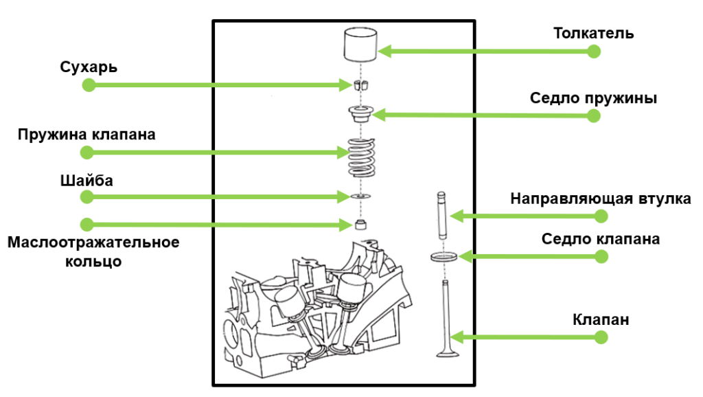
The main elements of the mechanism:
- intake and exhaust valves - designed to enter the air-fuel mixture and exhaust gases from the combustion chamber;
- guide bushings - ensure the exact direction of movement of the valves;
- spring - returns the valve to its original position;
- valve seat - the place of contact of the plate with the cylinder head;
- crackers - serve as a support for the spring and fix the entire structure);
- valve stem seals or oil slinger rings - prevents oil from entering the cylinder;
- pusher - transmits pressure from the camshaft cam.
The cams on the camshaft press on the valves, which are spring-loaded to return to their original position. The spring is attached to the rod with crackers and a spring plate. To dampen resonant vibrations, not one, but two springs with versatile winding can be installed on the rod.
The guide sleeve is a cylindrical piece. It reduces friction and ensures smooth and correct operation of the rod. During operation, these parts are also subject to stress and temperature. Therefore, wear-resistant and heat-resistant alloys are used for their manufacture. Exhaust and intake valve bushings are slightly different due to the difference in load.
How the valve mechanism works
Valves are constantly exposed to high temperatures and pressures. This requires special attention to the design and materials of these parts. This is especially true of the exhaust group, since hot gases exit through it. The exhaust valve plate on gasoline engines can be heated up to 800˚C - 900˚C, and on diesel engines 500˚C - 700C. The load on the inlet valve plate is several times less, but reaches 300˚С, which is also quite a lot.
Therefore, heat-resistant metal alloys with alloying additives are used in their production. In addition, exhaust valves typically have a sodium-filled hollow stem. This is necessary for better thermoregulation and cooling of the plate. The sodium inside the rod melts, flows, and takes some of the heat from the plate and transfers it to the rod. In this way, overheating of the part can be avoided.
During operation, carbon deposits may form on the saddle. To prevent this from happening, designs are used to rotate the valve. The seat is a high strength steel alloy ring that is pressed directly into the cylinder head for tighter contact.
In addition, for the correct operation of the mechanism, it is necessary to observe the regulated thermal gap. High temperatures cause parts to expand, which can cause the valve to malfunction. The gap between the camshaft cams and the pushers is adjusted by selecting special metal washers of a certain thickness or the pushers themselves (glasses). If the engine uses hydraulic lifters, then the gap is automatically adjusted.
A very large clearance prevents the valve from fully opening and therefore the cylinders will fill with fresh mixture less efficiently. A small gap (or lack of it) will not allow the valves to close completely, which will lead to valve burnout and a decrease in engine compression.
Classification by number of valves
The classic version of the four-stroke engine requires only two valves per cylinder to operate. But modern engines face more and more demands in terms of power, fuel consumption and respect for the environment, so this is no longer enough for them. Since the more valves, the more efficient it will be to fill the cylinder with a new charge. At various times, the following schemes were tested on engines:
- three-valve (inlet - 2, outlet - 1);
- four-valve (inlet - 2, exhaust - 2);
- five-valve (inlet - 3, exhaust - 2).
Better filling and cleaning of cylinders is achieved by more valves per cylinder. But this complicates the design of the engine.
Today, the most popular engines with 4 valves per cylinder. The first of these engines appeared in 1912 on the Peugeot Gran Prix. At that time, this solution was not widely used, but since 1970 mass-produced cars with such a number of valves began to be actively produced.
Drive design
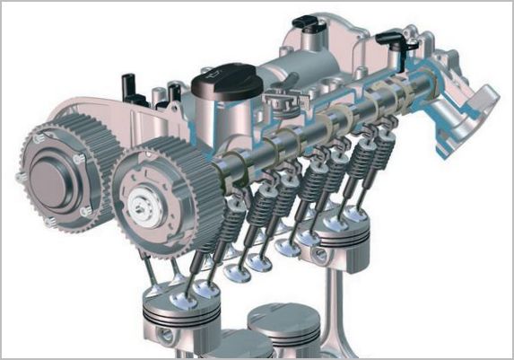
The camshaft and timing drive are responsible for the correct and timely operation of the valve mechanism. The design and number of camshafts for each type of engine are selected individually. A part is a shaft on which cams of a certain shape are located. When they turn, they put pressure on the pushrods, hydraulic lifters or rocker arms and open the valves. The type of circuit depends on the specific engine.
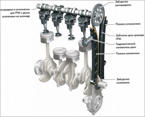
The camshaft is located directly in the cylinder head. The drive to it comes from the crankshaft. It can be a chain, belt or gear. The most reliable is chain, but it requires auxiliary devices. For example, a chain vibration damper (damper) and a tensioner. The speed of rotation of the camshaft is half the speed of rotation of the crankshaft. This ensures their coordinated work.
The number of camshafts depends on the number of valves. There are two main schemes:
- SOHC - with one shaft;
- DOHC - two shafts.
Only two valves are enough for one camshaft. It rotates and alternately opens the intake and exhaust valves. The most common four-valve engines have two camshafts. One guarantees the operation of the intake valves, and the other guarantees the exhaust valves. V-type engines are equipped with four camshafts. Two on each side.
The camshaft cams do not push the valve stem directly. There are several types of "intermediaries":
- roller levers (rocker arm);
- mechanical pushers (glasses);
- hydraulic pushers.
Roller levers are the preferred arrangement. The so-called rocker arms swing on plug-in axles and put pressure on the hydraulic pusher. To reduce friction, a roller is provided on the lever that makes direct contact with the cam.
In another scheme, hydraulic pushers (gap compensators) are used, which are located directly on the rod. Hydraulic compensators automatically adjust the thermal gap and provide a smoother and quieter operation of the mechanism. This small part consists of a cylinder with a piston and spring, oil passages and a check valve. The hydraulic pusher is powered by oil supplied from the engine lubrication system.
Mechanical pushers (glasses) are closed bushings on one side. They are installed in the cylinder head housing and directly transfer the force to the valve stem. Its main disadvantages are the need to periodically adjust the gaps and knocks when working with a cold engine.
Noise at work
The main valve malfunction is a knock on a cold or hot engine. Knocking on a cold engine disappears after the temperature rises. When they heat up and expand, the thermal gap closes. In addition, the viscosity of the oil, which does not flow in the right volume into the hydraulic lifters, may be the cause. Contamination of the oil channels of the compensator can also be the cause of the characteristic tapping.
Valves can knock on a hot engine due to low oil pressure in the lubrication system, a dirty oil filter, or an incorrect thermal clearance. It is also necessary to take into account the natural wear of parts. Malfunctions may be in the valve mechanism itself (wear of the spring, guide sleeve, hydraulic tappets, etc.).
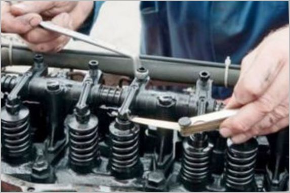
Clearance adjustment
Adjustments are made only on a cold engine. The current thermal gap is determined by special flat metal probes of different thicknesses. To change the gap on the rocker arms there is a special adjusting screw that turns. In systems with a pusher or shims, adjustment is made by selecting parts of the required thickness.
Consider a step-by-step process for adjusting valves for engines with pushers (cups) or washers:
- Remove the engine valve cover.
- Turn the crankshaft so that the piston of the first cylinder is at top dead center. If it is difficult to do this by marks, you can unscrew the spark plug and insert a screwdriver into the well. Its maximum upward movement will be dead center.
- Using a set of feeler gauges, measure the valve clearance under the cams that are not pressing on the tappets. The probe should have a tight, but not too free play. Record the valve number and clearance value.
- Rotate the crankshaft one revolution (360°) to bring the 4th cylinder piston to TDC. Measure the clearance under the rest of the valves. Write down the data.
- Check which valves are out of tolerance. If there are any, select the pushers of the desired thickness, remove the camshafts and install new glasses. This completes the procedure.
It is recommended to check the gaps every 50-80 thousand kilometers. Standard clearance values can be found in the vehicle repair manual.
Please note that intake and exhaust valve clearances may sometimes differ.
A properly adjusted and tuned gas distribution mechanism will ensure smooth and even operation of the internal combustion engine. This will also have a positive effect on engine resources and driver comfort.