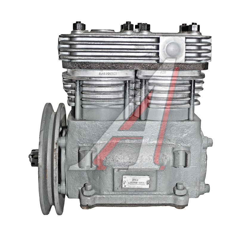
MAZ compressor
Check the tension of the compressor drive belt daily. The strap should be stretched so that when you press the middle of the short branch of the strap with a force of 3 kg, its deflection is 5-8 mm. If the belt flexes more or less than the specified value, adjust its tension, as under or over tension can lead to premature wear of the belt.
The setup procedure is as follows:
- loosen the tensioner pulley shaft nut and the tensioner bolt nut;
- turning the tensioner bolt clockwise, adjust the belt tension;
- tighten the nuts holding the tensioner bolt axle.
The total oil consumption of the compressor depends on the reliability of the sealing of the oil supply channel in the back cover of the compressor. Therefore, periodically after 10-000 km of the car, remove the rear cover and check the reliability of the seal.
If necessary, the parts of the sealing device are washed in diesel fuel and thoroughly cleaned of coke oil.
After 40-000 km of operation, remove the compressor head, clean pistons, valves, seats, springs and air passages from carbon deposits, remove and blow out the suction hose. At the same time check the condition of the unloader and the tightness of the valves. Lappe worn valves that do not seal to the seats, and if this fails, replace them with new ones. New valves must also be lapped.
When checking the unloader, pay attention to the movement of the plungers in the bushings, which must return to their original position without binding under the action of the springs. It is also required to check the tightness of the connection between the plunger and the bushing. The reason for insufficient tightening may be a worn rubber piston ring, which in this case must be replaced with a new one.
When checking and replacing rings, do not remove the compressor head, but remove the air supply pipe, remove the rocker arm and spring. The plunger is pulled out of the socket with a wire hook, which is inserted into a hole with a diameter of 2,5 mm located at the end of the plunger, or air is supplied to the horizontal channel of the injection device.
Lubricate the plungers with CIATIM-201 GOST 6267-59 grease before installing them in place.
Complete drainage of water from the head and cylinder block of the compressor is carried out through a valve valve located in the knee of the compressor outlet pipe. If a knock occurs in the compressor due to an increase in the gap between the connecting rod bearings and the crankshaft journals, replace the compressor connecting rod bearings.
Read also Driving a car ZIL-131
If the compressor does not provide the required pressure in the system, first of all check the condition of the pipes and their connections, as well as the tightness of the valves and pressure regulator. The tightness is checked by ear or, if the air leakage is small, with a soapy solution. Probable causes of air leakage may be diaphragm leaks, which will appear through the threaded connections in the upper part of the body or through the hole in the lower part of the body if the valve is not tight. Replace leaking parts.
MAZ compressor device
The compressor (Fig. 102) is a two-cylinder piston driven by a V-belt from the fan pulley. The cylinder head and crankcase are bolted to the cylinder block, and the crankcase is bolted to the engine. In the middle part of the cylinder block there is a cavity in which the compressor unloader is located.
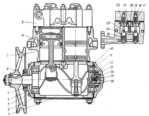
Rice. 102.MAZ Compressor:
1 - transport plug of the compressor crankcase; 2 - compressor crankcase; 3 and 11 - bearings; 4 - front cover of the compressor; 5 - stuffing box; 6 - pulley; 7 - compressor cylinder block; 8 - piston with connecting rod; 9 — a head of the block of cylinders of the compressor; 10 - retaining ring; 12 - thrust nut; 13 - rear cover of the compressor crankcase; 14 - sealant; 15 - spring seal; 16 - crankshaft; 17 - intake valve spring; 18 - inlet valve; 19 - intake valve guide; 20 - rocker arm guide spring; 21 - rocker spring; 22 - inlet valve stem; 23 - rocker; 24 - plunger; 25 - sealing ring
The compressor lubrication system is mixed. Oil is supplied under pressure from the engine oil line to the connecting rod bearings. The oil flowing from the connecting rod bearings is sprayed, turns into an oil mist and lubricates the cylinder mirror.
The compressor coolant flows through the pipeline from the engine cooling system to the cylinder block, from there to the cylinder head and is discharged into the suction cavity of the water pump.
Read also Technical characteristics of the KamAZ engine
The air entering the compressor enters below the reed inlet valves 18 located in the cylinder block. The inlet valves are placed in guides 19, which limit their lateral displacement. From above, the valves are pressed against the seat by the intake valve spring. The upward movement of the valve is limited by the spring guide rod.
As the piston moves down, a vacuum is created in the cylinder above it. The channel communicates the space above the piston with the cavity above the intake valve. Thus, the air entering the compressor overcomes the spring force of the intake valve 17, lifts it and rushes into the cylinder behind the piston. When the piston moves up, the air is compressed, overcoming the force of the reset valve spring, knocks it off the seat and enters the cavities formed from the head through the nozzles in the pneumatic system of the car.
Unloading the compressor by bypassing air through the open inlet valves is carried out as follows.
When the maximum pressure of 7–7,5 kg/cm2 is reached in the pneumatic system, the pressure regulator is activated, which simultaneously passes compressed air into the horizontal channel of the unloader.
Under the action of increased pressure, the pistons 24 together with the rods 22 rise, overcoming the pressure of the springs of the intake valves, and the rocker arms 23 simultaneously tear off both intake valves from the seat. Air flows from one cylinder to another into the gaps formed through the channels, in connection with which the supply of compressed air to the pneumatic system of the car is stopped.
After reducing the air pressure in the system, its pressure in the horizontal channel communicated with the pressure regulator decreases, the plungers and unloader rods lower under the action of the springs, the inlet valves settle on their seats, and the process of forcing air into the pneumatic system is repeated again.
Most of the time, the compressor runs unloaded, pumping air from one cylinder to another. Air is injected into the pneumatic system only when the pressure drops below 6,5–6,8 kg/cm2. This ensures that the pressure in the pneumatic system is limited and reduces wear on the compressor parts.