Control lamps of the instrument panel Maz 5440
Content
Designation of control lamps MAZ.
It is extremely important to monitor the condition of the MAZ sensors and control lights on the instrument panel of the truck.
Today we will tell you all about the purpose of these elements.
Do not forget that it is easy to order accessories for the MAZ dashboard on our website.
Deciphering the right side of the shield
On the right, control lights on the MAZ panel, reflecting:
- Pressure drop in brake circuits;
- Battery level;
- Reduce the degree of oil pressure in the engine;
- Insufficient coolant level;
- Inclusion of blocking of cross-axle differential;
- Dirty oil filter;
- ABS condition on the trailer;
- EDS operation;
- starter glow plugs;
- Reaching the emergency mark on the oil level;
- PBS and ABS diagnostic mode;
- ABS control;
- Dirty air filter;
- Fluid level in the power steering system;
- Emergency temperature increase in the engine cooling system.
The decoding of the MAZ Zubrenok dashboard lamps also includes values that are displayed on the right side of the panel. Here are the switches for the operation of the fan in the cabin, light, differential lock and Check Engine light.
In the same part there are switches for the rear fog lamp, mirror heating, ABS mode, TEMPOSET, PBS.
Next come the instrument illumination rheostat, the alarm switch, the battery switch and the thermostat that controls the heater (if such a unit is installed).

MAZ control lamps, as well as instrument panels, are easy to find in the catalog. We guarantee fast delivery, reasonable price and the best quality of spare parts.
Source
Symbols of switches and control indicators MAZ 5340M4, 5550M4, 6312M4 (Mercedes, Euro-6).
Symbols of switches and control indicators MAZ 5340M4, 5550M4, 6312M4 (Mercedes, Euro-6).
Symbols for switches and control indicators MAZ 5340M4, 5550M4, 6312M4 (Mercedes, Euro-6).
1 - High beam / high beam.
2 - Dipped beam.
3 - Headlight cleaner.
4 - Manual adjustment of the direction of the headlights.
5 - front fog lights.
6 - Rear fog lights.
7 — Focus.
8 - headlight hook.
10 - Internal lighting.
11 - Internal directional lighting.
12 - Working lighting.
13 - Main light switch.
14 - Failure of outdoor lighting lamps.
15 - Lighting devices.
16 - Flashing beacon.
17 - turn signals.
18 - Turn signals of the first trailer.
19 - turn signals for the second trailer.
20 - Alarm signal.
21 - Beacon to illuminate the working area.
22 - Headlights.
23 - Marker lights.
24 - Marker lights.
25 - Parking brake.
26 - Malfunction of the brake system.
27 - Malfunction of the brake system, primary circuit.
28 - Malfunction of the brake system, second circuit.
29 — Retarder.
30 - Wipers.
31 - Wipers. Intermittent work.
32 - windshield washer.
33 - Windscreen wipers and washers.
34 - Windshield washer fluid level.
35 - Blowing / defrosting the windshield.
36 - Heated windshield.
37 - Air conditioning system.
38 - Fan.
39 - Internal heating.
40 - Additional internal heating.
41 - Overturning of the cargo platform.
42 - Overturning the cargo platform of the trailer.
43 - Lowering the tailgate.
44 - Overturning the rear door of the trailer.
45 - Water temperature in the engine.
46 - Engine oil.
47 - Oil temperature.
48 - Engine oil level.
49 - Engine oil filter.
50 - Engine coolant level.
51 - engine coolant heating.
See also: blood oxygen meter
52 - Engine water fan.
53 - Fuel.
54 - Fuel temperature.
55 - Fuel filter.
56 - Fuel heating.
57 - Rear axle differential lock.
58 - Front axle differential lock.
59 - Locking the central differential of the rear axles.
60 - Blocking the central differential of the transfer case.
61 - Rear axle differential lock.
62 - Central differential lock.
63 - Front axle differential lock.
64 - Activate the center differential lock.
65 - Enable cross-axle differential lock.
66 - Cardan shaft.
67 - Cardan shaft No. 1.
68 - Cardan shaft No. 2.
69 — Gearbox reducer.
70 — Winch.
71 - Sound signal.
72 - Neutral.
73 — Battery charging.
74 - Battery failure.
75 - Fuse box.
76 - Heated outside rear-view mirror.
Tractor 77-ABS.
78 — Traction control.
79 - Trailer ABS failure.
80 - trailer ABS malfunction.
81 - suspension malfunction.
82 - Transport position.
83 - Startup help.
84 - Elevator axis.
85 - Stop the engine.
86 - Starting the engine.
87 - Engine air filter.
88 - Heating the air entering the engine.
89 - Low level of ammonia solution.
90 - Exhaust system malfunction.
91 - Monitoring and diagnostics of the ECS engine.
92 - Signaling device for information about the ESU engine.
93 - Gear shift "Up".
94 - Gear shift "Down".
95 - Cruise control.
96 - Diesel preheating.
97 - transmission malfunction.
98 - Gearbox divider.
99 - Exceeding the axial load.
100 - blocked.
101 - steering malfunction.
102 - Go up to the platform.
103 - Lowering the platform.
104 - Vehicle/trailer platform control.
105 - Monitoring the condition of the hitch.
106 - Activation of the "Startup Assistance" mode ESUPP.
107 - Clogged particulate filter.
108 - MIL command.
109 - Emergency address, primary circuit.
110 - Emergency address, second circuit.
111 - Emergency oil temperature in the gearbox.
112 - Limited mode.
113 - Signaling system of exchange rate stability.
Source
3 Controls and control devices
3. CONTROL AND CONTROL DEVICES
The location of the controls and control devices is shown in Figures 9, 10, 11.
Crane handle for parking and emergency brakes
It is located to the right of the steering column under the instrument panel. The handle is fixed in two extreme positions. In the fixed position of the lower end of the handle, the parking brake is activated, which is released when the lever is moved to the upper fixed position. When holding the handle in any intermediate position (non-fixed), the emergency brake is activated.
When you push the end of the handle all the way down and move it even lower, the trailer is released and the tractor brakes are checked to keep the road train on the slope.
Secondary brake control valve button
It is located on the cab floor to the left of the driver.
When the button is pressed, the throttle valve, which closes the bore in the exhaust pipe, creates a back pressure in the engine exhaust system. In this case, the fuel supply is stopped.
Steering wheel with protective column support and height and tilt adjustment.
Adjustments are made by pressing the pedal, which is located on the steering column mounting bracket. Once the steering wheel is in a comfortable position, release the pedal.
See also: electric pedicure at home
Interlock - starter and instrument switch on the steering column with an anti-theft device. The key is inserted and removed from the lock in position III (Fig. 9).
To unlock the steering column, you must insert the key into the lock switch, and to avoid breaking the key, turn the steering wheel slightly from left to right, then turn the key clockwise to the “0” position.
When the key is removed from the lock-switch (from position III), the locking device of the lock is activated. To lock the steering column axle, turn the steering wheel slightly to the left or right.
Other key positions in the castle:
0 - neutral position (fixed). Instrument and starting circuits are disconnected, the engine is turned off;
1 - consumers and circuits are on (fixed position);
II - devices, consumers and starting circuits are on (non-fixed position).
The wiper switch 3 (Fig. 9) is located on the right side of the steering column. It has the following positions in the horizontal plane:
- 0 - neutral (fixed);
- 1 (fixed) - the wiper is on at low speed;
- II (fixed) - wiper on at high speed:
- Ill (fixed) - the wiper works in intermittent mode.
- IV (not fixed) - the windshield washer is on with the simultaneous inclusion of the wipers at low speed.
When you press the handle from the end, a pneumatic sound signal is triggered at any position of the handle.
The handle 2 for turning on the direction indicators, dipped and main beam is located on the steering column, on the left side. It has the following provisions:
In the horizontal plane:
0 - neutral (fixed);
1 (permanent): Good direction indicators are on. The indicators turn off automatically.
II (not fixed) - the right turn signals light up briefly;
III (not fixed) - the left turn signals turn on briefly;
IV (permanent) - left turn indicators are on. Indicators turn off automatically, Vertical:
V (not fixed) - short-term inclusion of high beam;
VI (permanently) - high beam is on;
01 (fixed) - low beam is on when the headlights are turned on by the main switch. When the handle is pressed from the end, an electric sound signal is switched on at any position of the handle.
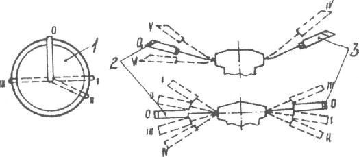
Figure 9. Controls
1 - ignition lock and devices with an anti-theft device; 2 - switch for headlights, direction indicators, electric signal; 3 - wiper, windshield washer and pneumatic signal switch
Tachometer 29 (Fig. 10) is a device that indicates the speed of the engine crankshaft. The tachometer scale has the following colored zones:
- green solid zone - the optimal range of economical operation of the engine;
- flashing green zone - range of economical engine operation;
- solid red zone - engine crankshaft speed range in which engine operation is not allowed;
- the area of red dots - the range of crankshaft speed in which short-term engine operation is allowed.
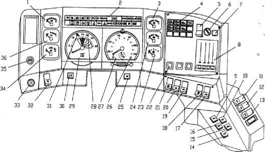
Figure 10. Toolbar
1 - voltage indicator; 2 - lamps for monitoring the operating mode (see Figure 11); 3 - air pressure sensor in the front circuit of the pneumatic brake actuator; 4 - control lamps of electronic systems (see section 4.9, fig. 70); 5 - heating mode switch (upper position - cab interior heating; middle position - combined engine and passenger compartment heating; lower position - engine heating); 6 - fan speed switch; 7 - button for turning on the air conditioner (if installed): 8 - control panel for the heating system *; 9.10 - cabin lighting switches; 11 - cross-axle differential lock switch; 12 - switch controlled blocking OSB semi-trailer; 13 — the switch of blocking of interaxal differential; 14 - ACP operation mode switch; 15 - switch of the second transport position; 16 - ABS mode switch; 17 - clutch headlight switch; 18 - mirror heating switch; 19 - change front / rear fog lights (upper position - off; middle - front; bottom - rear and front); 20 - road train signal switch; 21 - fan clutch switch (with YaMZ engine, upper position - off, middle - automatic clutch engagement, lower - forced engagement); 22 - TEMPOSET mode switch; 23 - fuel gauge; 24 - air pressure sensor in the rear circuit of the pneumatic brake actuator; 25 — EFU power button (with YaMZ engine); 26 — a control lamp of excess of speed; 27 - tachograph; 28 — a control lamp of inclusion of a range of a transmission (MAN); 29 - tachometer; 30 - button - AKV switch; 31 - control lamp for switching on the demultiplier (YaMZ), divider (MAN) of the gearbox; 32 - main light switch (upper position - off; middle - dimensions; lower - dipped beam); 33 - alarm switch: 34 - coolant temperature gauge; 35 - instrument lighting rheostat; 36 - oil pressure indicator in the engine lubrication system 32 - main light switch (upper position - off; middle - dimensions; lower - dipped beam); 33 - alarm switch: 34 - coolant temperature gauge; 35 - instrument lighting rheostat; 36 - oil pressure indicator in the engine lubrication system 32 - main light switch (upper position - off; middle - dimensions; lower - dipped beam); 33 - alarm switch: 34 - coolant temperature gauge; 35 - instrument lighting rheostat; 36 - oil pressure indicator in the engine lubrication system
See also: The content of precious metals in medical devices
* The heating, ventilation and air conditioning system of the cabin is described in the section "Cab" (see.
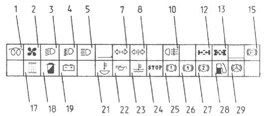
Figure 11. Location of control lamps on the instrument panel
1 - engine preheating is on, 2 - fan clutch is on (for the YaMZ engine); 3 — inclusion of a passing beam of headlights; 4 - turn on the light of the front fog lights; 5 - switching on the high beam; 7 - turn on the car turn signal; 8 - turn on the trailer turn signal; 10 - turn on the rear fog lamp, 12 - turn on the cross-axle differential lock; 13 — inclusion of blocking of interaxal differential; 15 - the inclusion of the parking brake; 17 - clogged air filter (for the YaMZ engine); 18 - blockage of the oil filter (for the YaMZ engine); 19 - battery discharge; 2 1 - lower the coolant level; 22 - oil pressure drop in the engine; 23 - emergency temperature in the engine cooling system; 24 - main alarm; 25 - service brake malfunction; 26 - air pressure drop in the front brake circuit; 27 - air pressure drop in the rear brake circuit, 28 - the amount of fuel is less than the reserve; 29 - lower the fluid level in the power steering
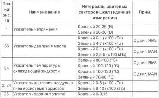
Arrows 1, 36, 34, 3, 24, 23 (Figure 10) have colored zones, the numerical value of the intervals of which is shown below.
The tachometer may have a counter for the total revolutions of the engine crankshaft.
30 battery switch remote control button. When the battery switch is turned on, the arrow on the voltage indicator shows the voltage of the on-board network.
It is necessary to disconnect batteries in car parks, as well as disconnect electricity consumers in emergency situations.
In case of failure of the remote control, the switch can be turned on or off by pressing the button on the switch body, located on the front or back of the battery compartment.
Tachograph 27 (Figure 10) is a device that displays the speed, current time and total distance traveled. It records (in encrypted form) the speed of movement, the distance traveled and the mode of operation of drivers (one or two) on a special disk.