3D design course in 360. Cylinders - lesson 2
Content
In the first part of the 3D programming course in Autodesk Fusion 360, we got acquainted with the options that allow you to create the simplest forms. We tried ways to add new elements to them and make holes. In the second part of the course, we will expand the acquired skills to the creation of rotating bodies. Using this knowledge, we will create useful connectors, for example, for plastic pipes often used in workshops (1).
1. Examples of standard connectors for water supply networks.
Plastic tubing is often used in home workshops due to its wide availability and affordable price. All over the world, various pipe structures of various diameters are being created - from drinking straws, through pipes for water supply and electrical installations, to sewer systems. Even with the plumbing connectors and taps available at craft stores, a lot can be done (2, 3).
2. Several models of connectors made for DIY enthusiasts.
3. You can make really unusual designs out of them!
The possibilities are really huge, and access to a special type of connectors multiplies them even more. In the Anglo-Saxon countries, there are connectors on the market specifically designed for - but buying them abroad seriously undermines the economic sense of the whole project ... Nothing! After all, you can easily design and print at home even those accessories that cannot be bought in America! After the last lesson of our course, this should not be a problem.
4. In practice, these are likely to be more practical models.
In the beginning, something simple - a connector called a coupling
This is the simplest of fasteners. As in the previous lesson, I recommend starting by creating a sketch on one of the planes, drawing a circle centered on the center of the coordinate system. The diameter of its ends should correspond to the size of the inner diameter of the pipes that we plan to connect (in the described case, these will be electric pipes with a diameter of 26,60 mm - thinner, cheaper than plumbing, but extremely poor fittings suitable for DIY enthusiasts).
5-6. Replacing even the main connectors of the system with our own - internal ones - will make the connections more aesthetic, will enable better installation of any casings or cladding - and it will also come out much cheaper!
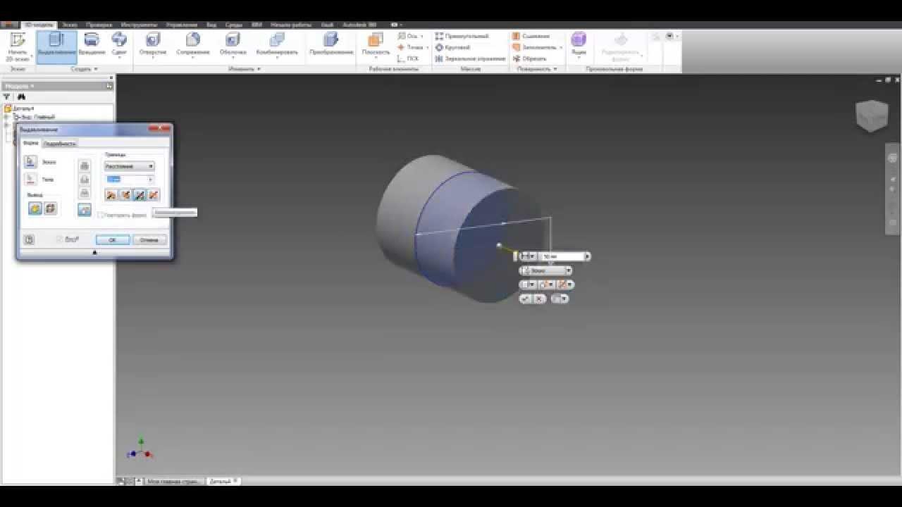
Using the option already known from the previous lesson, the circle should be drawn upwards. Find the parameter in the auxiliary window and change its setting to Symmetric. You must make this change before you can commit the solid extrude function. Due to this, the designed connector will be centered on the sketch plane (7). This will come in handy in the next step.
Now we create a second sketch in the same plane as the previous drawing. The first sketch will be automatically hidden - its display can be turned on again by finding the tab in the tree on the left side. After expanding, a list of all the sketches in the project will appear - click the light bulb next to the name of the sketch, and the selected sketch will become visible again.
The next circle should also be centered at the center of the coordinate system. This time its diameter will be 28,10 mm (this corresponds to the outer diameter of the pipes). In the auxiliary window, change the mode of creating a solid body from cutting to adding (function is the last parameter in the window). We repeat the operation as with the previous circle, but this time the extrusion value does not have to be large (just a few millimeters is enough).
8. Simple control - known from the previous edition of the course.
9. Finished and rendered clutch.
The connector would be ready, but it's worth reducing the amount of plastic needed to print it - it's definitely more economical and more environmentally friendly! So we hollow out the middle of the connector - a wall of a few mm is enough for a coupling. This can be done in the same way as with the key ring hole from the previous part of the course.
Starting to sketch the circle, we draw a circle at one end of the connector and cut it through the entire model. Immediately better (9)! When designing models for printing, it is also worth considering the accuracy of the printer and taking it into account in the dimensions of the project. This, however, depends on the hardware being used, so there is no single rule that will work in all cases.
Time for something a little more complex - the 90° elbow.o
We will start designing this element with a sketch on any plane. In this case, it is also worth starting from the center of the coordinate system. We'll start by drawing two equal lines perpendicular to each other. This will help the grid on the background of the sheet, to which the drawn lines “stick”.
10. Create a path for the elbow.
Keeping lines even every time can be a pain, especially if there are more of them. An auxiliary window comes to the rescue, stuck to the right side of the screen (it can be minimized by default). After expanding it (using two arrows above the text), two lists appear: .
11. Add a classic profile.
With both drawn lines selected, we look for Equal to options in the second list. After clicking, you can set the ratio between the line lengths. In the figure, an “=” sign will appear next to the line. It remains to round off the sketch so that it resembles an elbow. We will use the options from the tab's dropdown list. After selecting this option, click the connection point of the drawn lines, enter a value for the radius and confirm the selection by pressing Enter. This is how the so-called track happens.
12. Cut so that the connector fits inside the tube.
Now you will need an elbow profile. Close the current sketch by clicking on the option from the last tab (). Again we create a new sketch - the choice of the plane is crucial here. This should be a plane perpendicular to the one on which the previous sketch was. We draw a circle (with a diameter of 28,10 mm), like the previous ones (with a center in the center of the coordinate system), and at the same time at the beginning of the previously drawn path. After drawing a circle, close the sketch.
13. Such an elbow could really connect pipes - but why so much plastic?
Select an option from the tab's drop-down list. An auxiliary window will open in which we must select a profile and a path. If thumbnails disappear from the workspace, they can be selected from the tree on the left side of the tab.
In the auxiliary window, the option next to the inscription is highlighted - that means we select the profile, i.e. second sketch. Then click the "Select" button below and choose the path i.e. first sketch. Operation confirmation creates a knee. Of course, the diameter of the profile can be anything - in the case of the elbow created for the purposes of this article, it is 28,10 mm (this is the outer diameter of the pipe).
14. We continue the topic - after all, it is worth remembering both ecology and the economy!
We want the sleeve to go inside the pipe (12), so its diameter should be the same as the diameter of the inner pipe (in this case 26,60 mm). We can achieve this effect by cutting the legs to the elbow. At the ends of the elbow we draw a circle with a diameter of 26,60 mm, and the second circle is already with a diameter greater than the outer diameter of the pipes. We create a pattern that will cut the connector to the appropriate diameter, leaving a bent fragment of the elbow with the outer diameter of the pipe.
Repeat this procedure on the other leg of the elbow. As with the first connector, we will now reduce the elbow. Just use the options on the tab. After selecting this option, select the ends that should be hollow and specify the width of the rim to be made. The discussed function removes one face and creates a "shell" from our model.
Made?
Voila! Elbow ready (15)!
15. Visualization of the finished elbow.
Okay, we got it! So, what is next?
The current lesson, while presenting the principles of creating simple ones, at the same time opens up the possibility of implementing similar projects. The "production" of more complex fasteners is as simple as described above (18). It is based on changing the angles between track lines or gluing another knee. The center extrusion operation is performed at the very end of the structure. An example is hex connectors (or hex keys), and we get it by changing the shape of the profile.
16. With the features you just learned, you could also create, for example, a hex wrench…
We have our models ready and we can save them to an equivalent file format (.stl). The model saved in this way can be opened in a special program that will prepare the file for printing. One of the most popular and free programs of this type is the Polish version.
17.… or another connector you need - the procedures are almost the same!
18. An example of a connector created using the operations of the current lesson.
Once installed, it will ask us for an application. It has a very clear interface and even a person who launches the program for the first time can easily cope with preparing a model for printing. Open the file with the model (File → Open file), in the right panel, set the material from which we will print, determine the accuracy and set additional options that improve print quality - all of them become additionally described after hovering over the inscription button.
19. A small preview of the topic of the next lesson.
Knowing how to design and print the created models, it remains only to test the acquired knowledge. Undoubtedly, it will be useful in the following lessons - a complete set of topics for the entire course is presented in the table below.
Course Plan 3 360D Design
• Lesson 1: Dragging Rigid Bodies (Keychains)
• Lesson 2: Solid Bodies (Pipe Connectors)
• Lesson 3: Spherical bodies (bearings)
• Lesson 4: Complex rigid bodies (structural elements of robots)
• Lesson 5: Simple mechanisms right away! (corner gears).
• Lesson 6: Prototype Models (Model of Construction Crane)
See also: