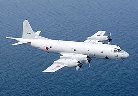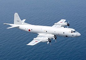
Lockheed R-3 Orion Part 1
The flight of the prototype YP-3V-1 took place on November 25, 1959 at the airfield of the Lockheed plant in Burbank, California.
In mid-May 2020, the VP-40 Fighting Marlins became the last US Navy patrol squadron to deploy P-3C Orions. The VP-40 also completed refitting of the Boeing P-8A Poseidon. P-3Cs are still in service with two reserve patrol squadrons, a training squadron, and two US Navy test squadrons. The last P-3Cs are due to be retired in 2023. Two years later, the EP-3E ARIES II electronic reconnaissance aircraft based on the P-3C will also end their service. Thus ends the extremely successful career of the P-3 Orion, which was adopted by the US Navy in 1962.
In August 1957, the US Naval Operations Command (US Navy) issued the so-called. aircraft type specification, No. 146. Specification No. 146 was for a new long-range maritime patrol aircraft to replace the then-used Lockheed P2V-5 Neptune patrol aircraft and Martin P5M-2S Marlin flying patrol boats. The new design was supposed to offer greater payload capacity, more space in the hull for anti-submarine defense (ASD) systems, as well as more places to control on-board equipment, greater range, radius of action and longer flight duration compared to P2V-. 5 . The bidders included Lockheed, Consolidated and Martin, all three with extensive experience building maritime patrol aircraft. Early on, due to insufficient range, the French Breguet Br.1150 Atlantique aircraft (also being offered to European NATO members as a successor to the Neptune aircraft) was dropped. It was clear that the US Navy was looking for a larger, preferably four-engined, design.
R-3A of the VP-47 squadron fires 127-mm unguided rockets "Zuni" from multi-barreled underwing launchers.
Lockheed then proposed a design that was a modification of the four-engine, 85-seat L-188A Electra airliner. Powered by proven Allison T56-A-10W turboprop engines (maximum power 3356 kW4500 hp), the Elektra was characterized by high cruising speed at high altitudes, on the one hand, and very good flight characteristics at low and low speeds, on the other. other hand. All this with a relatively moderate fuel consumption, providing a sufficient range. The aircraft had characteristic wing-shaped engine nacelles with elongated exhaust ducts. This design resulted in the engine's turbine exhaust generating an additional seven percent of power. The engines drove Hamilton Standard 54H60-77 metal propellers with a diameter of 4,1 m.
Unfortunately, the Electra did not achieve the expected commercial success due to a wing strength issue. There were three L-1959A crashes in 1960–188. The investigation showed that the phenomenon of "oscillatory flutter" of the wing was the cause of two crashes. The mounting design of the outboard motors was too weak to adequately dampen the vibrations caused by their enormous torque. The oscillations transmitted to the wingtips led to their increasing oscillations about the vertical axis. This, in turn, led to a breakdown of the structure and its separation. Lockheed immediately made appropriate changes to the design of the wing and engine mounts. These modifications have also been implemented in all copies already released. These actions, however, failed to salvage the Elektra's tattered prestige, and the costs of implementing modifications and lawsuits ultimately sealed the aircraft's fate. In 1961, after building 170 units, Lockheed ceased production of the L-188A.
Developed by Lockheed for the US Navy program, the Model 185 retained the wings, engines, and tail of the L-188A. The fuselage was shortened by 2,13 m (in the pre-wing section), which significantly reduced the curb weight of the aircraft. Under the front of the fuselage there is a bomb bay, closed by a double door, and under the rear of the fuselage there are four holes for ejection of acoustic buoys. The aircraft was supposed to have ten attachment points for outboard weapons - three under each wingtip and two under the fuselage of each wing. The six panels of cockpit glazing were replaced with five larger ones, improving visibility for the crew as well as from the Electra's cockpit. All windows of the passenger compartment were removed and four convex viewing windows were installed - two on both sides of the front of the fuselage and two on both sides of the rear.
The emergency exit door leading to the wings (with windows) on both sides of the fuselage is preserved, the left door is shifted towards the trailing edge of the wing. The left front passenger door was removed, leaving only the left rear door as the aircraft's front door. The nose cone of the Electra has been replaced with a new, larger and more pointed one. A magnetic anomaly detector (DMA) is installed at the end of the tail section. The detector and mount are 3,6 m long, so the total length of Orion is 1,5 m longer than that of Electra. On April 24, 1958, the Lockheed Model 185 was selected by the US Navy to bid for a new patrol aircraft.
The first prototype of the future "Orion" was built on the basis of the third production unit "Electra". It had the original non-shortened fuselage, but was equipped with mock-ups of the bomb bay and VUR. It was a sample designed for aerodynamic testing. The prototype, which received civil registration number N1883, first flew on August 19, 1958. On October 7, 1958, the Navy awarded Lockheed a contract to build the first functional prototype, designated the YP3V-1. It was built on the basis of N1883, which then received all the elements, systems and equipment provided for by the project. The aircraft re-flyed on November 25, 1959 at Burbank Lockheed, California. This time the YP3V-1 bore the US Navy serial number BuNo 148276. The Navy officially designated the new design as the P3V-1.
In the mid-1960s, the US Navy decided to start building seven pre-series units (BuNo 148883 - 148889). In November, the aircraft was officially named "Orion" in keeping with Lockheed's tradition of naming aircraft associated with mythology and astronomy. The flight of the first pre-production copy (BuNo 148883) took place on April 15, 1961 at the airfield in Burbank. Then began a period of various tests of the YaP3V-1 prototype and seven pre-production P3V-1 installations. In June 1961, the Naval Aviation Test Center (NATC) began the first phase of the Navy Preliminary Examination (NPE-1) at NAS Patuxent River, Maryland. Only the YP1V-3 prototype participated in the NPE-1 phase.
The second stage of testing (NPE-2) included testing of production units in operation. The Navy finished it in October 1961, directing the manufacturer to make minor design changes. The NPE-3 phase ended in March 1962, paving the way for final testing and design evaluation (Board of Inspection, BIS). During this phase, five P3V-1s were tested on the Patuxent River (BuNo 148884–148888) and one (BuNo 148889) was tested at the Naval Weapons Evaluation Center (NWEF) in Albux-Evaluquerque, New Mexico. Finally, on June 16th, 1962, the P3V-1 Orions were declared fully operational with US Navy squadrons.
P-3A
On September 18, 1962, the Pentagon introduced a new marking system for military aircraft. The P3V-1 designation was then changed to P-3A. The Lockheed plant in Burbank built a total of 157 P-3As. The US Navy was the sole recipient of this Orion model, which was not exported at the time of production.
R-3A had a crew of 13 people, including: pilot commander (KPP), co-pilot (PP2P), third pilot (PP3P), tactical coordinator (TAKKO), navigator (TAKNAV), radio operator (RO), mechanic deck ( FE1), second mechanics (FE2), the so-called. operator of non-acoustic systems, i.e. Radar and MAD (SS-3), two acoustic system operators (SS-1 and SS-2), an on-board technician (BT) and a gunsmith (ORD). The IFT technician was responsible for monitoring the operation and carrying out current repairs of systems and on-board devices (electronics), and the gunsmith was responsible, among other things, for preparing and dropping acoustic buoys. There were five officer positions in total - three pilots and two NFOs, i.e. Navy officers (TACCO and TACNAV) and eight non-commissioned officers.
The three-seat cockpit accommodated the pilot, the co-pilot, who sat to his right, and the flight engineer. The mechanic's seat was swivel and could slide on rails laid in the floor. Thanks to this, he could move from his seat (at the rear of the cockpit, from the starboard side) so that he could sit in the center, immediately behind the pilots' seats. The pilot was a Patrol Plane Commander (PPC). Behind the cockpit on the starboard side was the position of the second mechanic, and then the toilet. Behind the cockpit, on the port side, was the radio operator's office. Their positions were located on both sides of the hull at the height of the viewing windows. Thus, they could also act as observers. In the middle part of the hull, on the left side, there is a combat compartment of the Tactical Coordinator (TAKKO). There were five combat stations located next to each other, so that the operators sat sideways facing the direction of flight, facing the port side. The TACCO booth stood in the center. To his right were the operator of the airborne radar and the MAD system (SS-3) and the navigator. On the left side of TACCO there were two so-called acoustic sensor stations (SS-1 and SS-2).
The operators who occupied them operated and controlled the echolocation systems. The competencies of the pilot-in-command of the aircraft (CPC) and TACCO were mutually intertwined. TAKKO was responsible for the entire course and performance of the task, and it was he who asked the pilot the direction of action in the air. In practice, many tactical decisions were made by TACCO after consultation with the CPT. However, when the issue of flight or aircraft safety was at stake, the role of the pilot became paramount and he made the decision, for example, to terminate the mission. On the starboard side, opposite the operator's stations, there were cabinets with electronic devices. Behind the TACCO compartment, on the starboard side, there are acoustic buoys. Behind them, in the middle of the floor, is a three-hole, low-chest, size A buoy and a single, size B buoy, in the form of a tube sticking out of the floor. .
See also part Article II >>>
