Mercedes w203: fuses and relays
The Mercedes 203 C-Class is the second generation of the model range, which was produced in 2000, 2001, 2002, 2003, 2004, 2005, 2006 and 2007 with w203 sedan, s203 station wagon, coupe (C160, C180, C230, C240), C280, C320). During this time, the model has been redesigned. In this publication you will find information on the location of electronic control units, a detailed description of the fuses and relays Mercedes 203 with block diagrams and photo examples of their location. Pay attention to the fuses responsible for the cigarette lighter and fuel pump.
The location of the blocks and the location of the elements on them may differ from those shown and depend on the year of manufacture, the region of delivery and the level of electrical equipment of your car.
Location
General arrangement of electronic control units

Description
| one | Air conditioning / heating control unit - in the heating control panel |
| two | A/C/Heater Fan Control Module - Near the fan motor |
| 3 | Air purity sensor (air conditioning system) |
| 4 | Sunlight sensor (air conditioning system) |
| 5 | Antenna signal amplifier - 1, at the top of the rear window |
| 7 | Anti-theft control unit (built into the multifunction control unit) - left side of the trunk |
| eight | Vehicle inclination sensor (anti-theft system) - left side of trunk |
| nine | Anti-theft horn - behind wheel arch trim |
| ten | Volume change sensors (anti-theft system) |
| 11 | Audio block - in the navigation system |
| 12 | Audio Output Amplifier (If Equipped) - Right Trunk Side |
| thirteen | Additional heating control unit |
| 14 | Auxiliary Heater Remote Control Receiver - Under Dashboard (Rear Luggage Compartment) |
| fifteen | Accumulator battery |
| sixteen | Brake booster vacuum pump control unit |
| 17 | Central locking signal sensor (infrared) - on the driver's door handle |
| Eighteen | Diagnostic connector (DLC) |
| nineteen | Electric control box driver's door |
| twenty | Rear left door electric control box |
| 21 | Passenger door electric control unit |
| 22 | Rear right door electronics control unit |
| 23 | Fuse / relay box, engine compartment 1 |
| 24 | Fuse/Relay Box |
| 25 | Fuse/Relay Box, Trunk |
| 26 | Left headlight control unit (models with xenon headlights) |
| 27 | Right headlight control unit (models with xenon headlights) |
| 28 | Sound signals 1/2 - behind bars |
| 29 | Ignition lock control unit |
| 30 | Electronic immobilizer control unit (integrated with ignition lock control unit) |
| 31 | Turn Signal/Hazard Relay - In Multifunction Control Module 2 |
| 32 | Lighting control unit - behind the headlight switch |
| 3. 4 | Multifunction Control Module 1 - Connected to Engine Compartment Fuse/Relay Box - Functions: Interior Lights, Headlights, Horn, Wipers, A/C Pressure Control, Headlight Washers, Coolant Level, Brake Fluid Level, Thermometer, Power Outside Mirrors |
| 35 | Multifunction control unit 2 - connected by fuse / relay box, trunk - functions: central locking, fuel level, anti-theft system, alarm, heated rear window, taillights, trunk lid opener, rear wiper (wagon) |
| 36 | Navigation system control unit |
| 37 | Room temperature sensor |
| 38 | Parking system control unit - under the panel, in the rear of the trunk |
| 39 | Rain sensor - top center of windshield |
| 40 | Power seat control unit (with memory), front left - under the seat |
| 41 | Power seat control unit (with memory), front right - under the seat |
| 42 | Front seat heating control unit - in the switch box |
| 43 | Electronic transmission - sequential manual transmission |
| 44 | Side impact sensor on the left under the rear seat |
| Four five | Side impact sensor, right - under the rear seat |
| 46 | SRS electronic control unit |
| 47 | Steering column electric control unit - behind the steering wheel |
| 48 | Steering column lock control unit - built into the ignition lock control unit |
| 49 | Electric sunroof control |
| 50 | Body height sensor, front (models with xenon headlights) - front anti-roll bar |
| 51 | Body height sensor, rear (models with xenon headlights) - rear axle |
| 52 | Telephone network connection module - under the panel, in the rear of the trunk |
| 53 | Telephone interface control unit - under the panel, in the rear of the trunk |
| 54 | Handset - under the panel, in the rear of the trunk |
| 55 | Electric trailer control unit - under the panel, in the rear of the trunk |
| 56 | Electronic transmission control unit |
| 57 | Shift Control Module - Automatic Transmission Selector |
| 59 | Voice control unit - under the panel, in the rear of the trunk |
| 60 | Fuse / relay box, engine compartment 2 |
Location of fuse and relay boxes in Mercedes 203
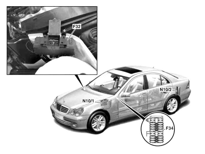
designation
- F32 - power fuse box
- F34 - Fuse box in the dashboard
- N10 / 1 - Fuse box and relay in the engine compartment
- N10 / 2 - Fuse box and trunk relay
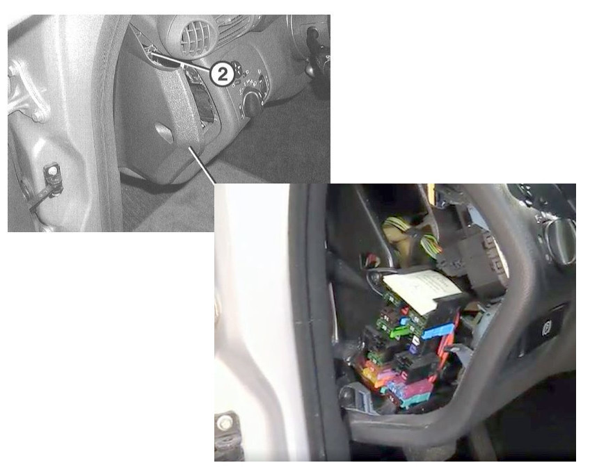
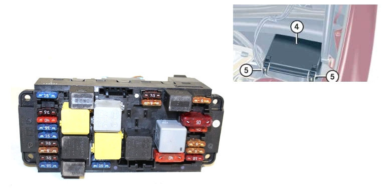
Block in the cabin
In the cab, the fuse box is located on the left side of the dashboard under a protective cover.
scheme
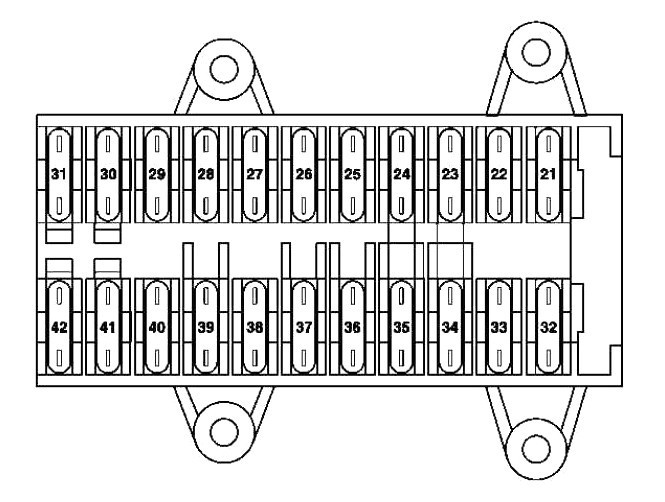
Goal
| 21 | 30A Left front door control unit |
| 22 | 30A Right front door control unit |
| 23 | 15A cigarette lighter |
| 24 | 7,5A CD player with changer (in glove box) |
| 25 | 30A Upper control panel control unit |
| 26 | 25A audio amplifier |
| 27 | 30A Power driver's seat control unit (with memory) |
| 28 | Spare fuse 30A |
| 29 | 30A Power driver's seat control unit (with memory) |
| Multifunctional control unit (taxi) | |
| 30 | Heater air circulation unit 40A |
| 31 | EIS 20A control unit |
| Ignition lock control unit | |
| 32 | 30A Left rear door control unit |
| 33 | 30A Right rear door control unit |
| 3. 4 | 7,5A terminal 30 socket |
| Before 31.05.01: | |
| Mobile phone and D2B transceiver (for built-in phone) | |
| Cell phone and TELE AID D2B transceiver (for built-in phone) | |
| Phone interface (for optional cell phone) | |
| Compensator CTEL (for additional cell) | |
| 15A Before 31.3.04: Power passenger seat control unit (with memory) | |
| Until 31.05.03/XNUMX/XNUMX, Taxi: Multifunction switch | |
| From 1.6.03, Taxi: Multifunction Switch | |
| As of 1.6.01, Police: Multifunctional control unit | |
| 30A From 1.4.04: Power passenger seat control unit (with memory) | |
| From 1.4.04, Taxi: Multifunction control unit | |
| 35 | 30A Up to 31.03.04: STH heater |
| 20A From 1.4.04: STH heater | |
| 36 | 30A Before 31.3.04, Police: additional power socket |
| Engines 15A 612.990 (up to 29.2.04): charge air cooler circulation pump | |
| From 1.4.04, Japan: Audio Interface Control Unit | |
| 7,5A universal mobile phone interface | |
| 37 | 25A air cooler circulation pump |
| Up to 29.2.04: Brake booster vacuum pump control unit | |
| 38 | 30A Before 29.2.04: Power passenger seat control unit (with memory) |
| From 1.4.04, Police: Multifunction control unit | |
| 39 | Spare fuse 30A |
| 40 | 7,5A Power passenger seat control unit (with memory) |
| Universal mobile phone interface | |
| cell phone split point | |
| Telephone interface | |
| Radiotelephone network compensator E | |
| From 1.6.01, MB phone: cell phone and transceiver | |
| As of 1.6.01 TELE AID: cellular communication and transceiver | |
| From 1.4.04, Japan: ECU | |
| 30A Up to 31.5.01: Multifunction control unit | |
| 41 | 7.5A Upper control panel control unit |
| Until 31.05.01/XNUMX/XNUMX: KLA control panel (automatic climate control) | |
| 15A From 1.6.01: KLA system control panel (Automatic climate control system) | |
| 42 | 7.5A Instrument cluster |
In the Mercedes 203, fuse 23 is responsible for the cigarette lighter. Another fuse is located in the block under the hood or in the trunk (USA).
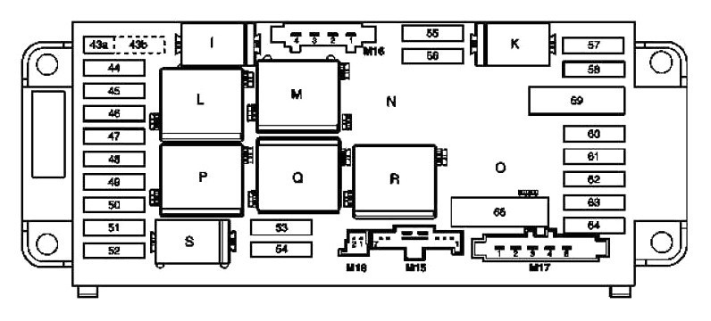
Block under the hood
Main unit
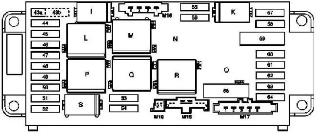
Under the hood in the engine compartment on the left side under the protective cover is the fuse and relay box.
scheme
transcribed
| 43a | 15A Horn relay |
| 43б | 15A Horn relay |
| 44 | 5A D2B-interface |
| Telephone interface | |
| Ferrule connector 15R | |
| TELE AID switchboard | |
| Four five | SRS control unit 7.5A |
| 46 | 40A Wiper On/Off Relay |
| Wiper Mode Relay 1/2 | |
| 47 | 15A Glove box lighting with sensor switch |
| Front cigarette lighter (illuminated) | |
| 48 | 15A Engines 612.990 (up to 31.3.04): Brake booster vacuum pump control unit |
| Motors 112, 113: Coupling sleeve protected by fuse 15 | |
| Engines 646, USA (until 31.03.04/30/XNUMX): Coupling with fuse XNUMX | |
| 646 engines (since 1.4.04): O2 sensor before catalytic converter | |
| 49 | SRS control unit 7.5A |
| 50 | Light switch module 5A |
| Engines 612 990 | |
| The final stage of the warm-up (until 31.03.04) | |
| Mass air flow sensor (from 1.4.04 to 30.11.04) | |
| 51 | 7,5A AAC (automatic air conditioning) with built-in auxiliary fan motor |
| Tool combination | |
| For AAS "comfort": | |
| AAC malfunction sensor | |
| Solar radiation sensor AAC (4 pcs) | |
| For all vehicles with xenon headlights: | |
| Left block headlight | |
| Right block headlight | |
| AMG: air cooler circulation pump | |
| 203.0 (until 31.7.01): SRS control unit | |
| 52 | 15A starter |
| 53 | Diesel engines 25A: |
| Starter relay | |
| Rear SAM control unit with relay and fuse box | |
| Engines 611/612/642/646: CDI control unit | |
| Gasoline engines 15A: | |
| Starter relay | |
| Rear SAM control unit with relay and fuse box | |
| Engines 111/271/272: ME control unit | |
| Engines 112/113: | |
| ME control unit | |
| Electrical cable connection terminal 87 M1e | |
| 54 | Engines 15A 271.940: |
| ME control unit | |
| Vent valve (USA) | |
| Container stop valve | |
| Engines 271.942: NOX control unit | |
| Engines 642/646: CDI control unit | |
| Engines 642/646: Termination of electrical cable terminals 30 circuits | |
| Engines 7,5A 611/612: CDI control unit | |
| Engines 611/612 (up to 30.11.04/XNUMX/XNUMX): Resistance in the ventilation duct | |
| 55 | Flywheel sensor 7,5A |
| Distronic: DTR control unit | |
| 722 gearbox: | |
| ETC control unit [EGS] (up to 31.5.04) | |
| Selector lever electronic control unit | |
| VGS control unit | |
| 716 gearbox: | |
| sequencetronic control unit | |
| Transmission Position Sensor | |
| 56 | 5A ESP and BAS control unit |
| Brake light switch | |
| 57 | 5A Steering wheel sensor (up to 31.5.02) |
| Electronic ignition control unit / sensor-switch that opens the starting circuit | |
| Steering column electronic module (as of 1.6.02) | |
| Engines 112/113: ME control unit | |
| 58 | 40A Transmission 716: Hydraulic pump |
| 59 | 50A ESP and BAS control unit |
| 60 | 40A ESP and BAS control unit |
| 61 | 15A Transmission 716: Sequentronic control unit |
| 62 | Diagnostic connector 5A |
| Lighting control module | |
| Brake light switch | |
| 63 | 5A lighting control module |
| 64 | 10A radio receiver |
| Radio and navigation | |
| Display and control unit for COMAND functions | |
| sixty five | 40A 112/113 Motors: Electric air pump |
| Relay | |
| Я | Horn relay |
| К | Terminal 87 relay, chassis |
| Л | Wiper Mode Relay 1/2 |
| METER | Relay terminal 15R |
| North | Pump control relay KSG |
| OR | Air Pump Relay (Engines 112, 113, 271) |
| П | Relay terminal 15 |
| Question | Wiper On/Off Relay |
| Р | Terminal 87 relay, motor |
| Yes | Starter relay |
Power unit
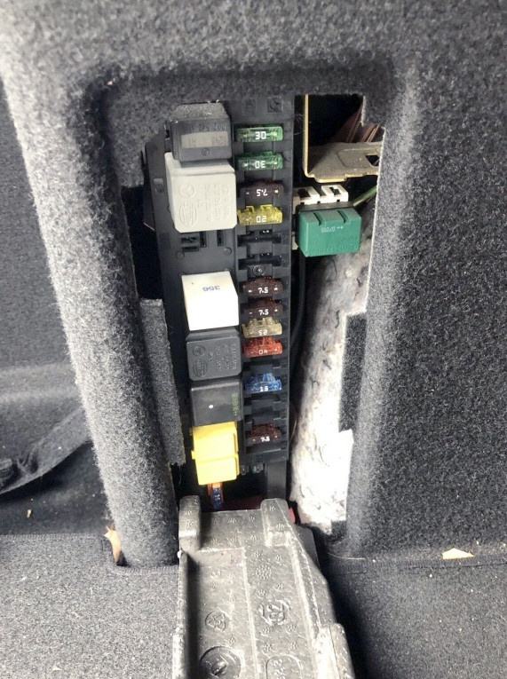
An additional high power fuse block in the form of fuse holders is installed next to the battery.
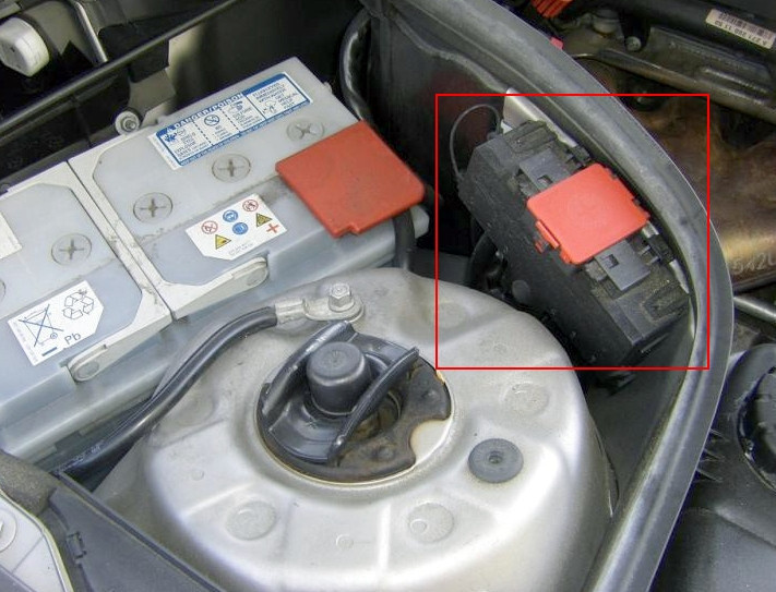
Photo example
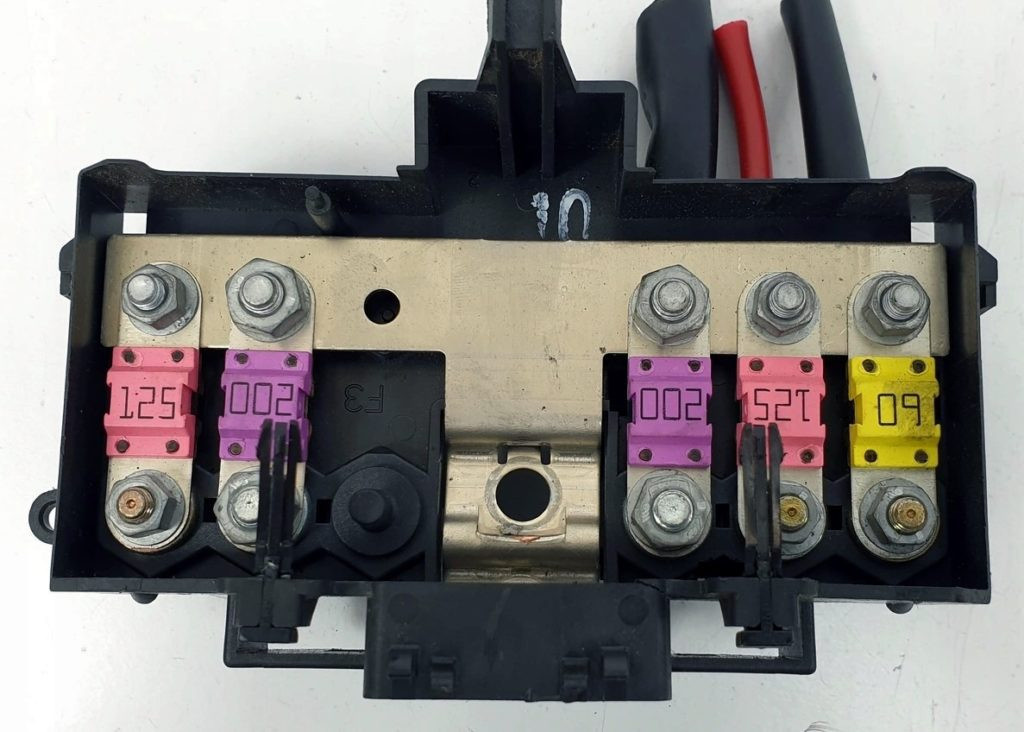
scheme
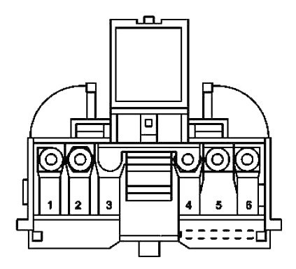
Description
- 125A fuse box in the instrument panel
- Control unit SAM 200A, rear
- 125A Additional fuse box
- 200A SAM control unit, front
- 125A Electric suction fan for engine and air conditioner with built-in regulator
Diesel engines: the final stage of preheating - 60A SAM control unit, front
block in trunk
It is located in the trunk, behind the upholstery.
scheme
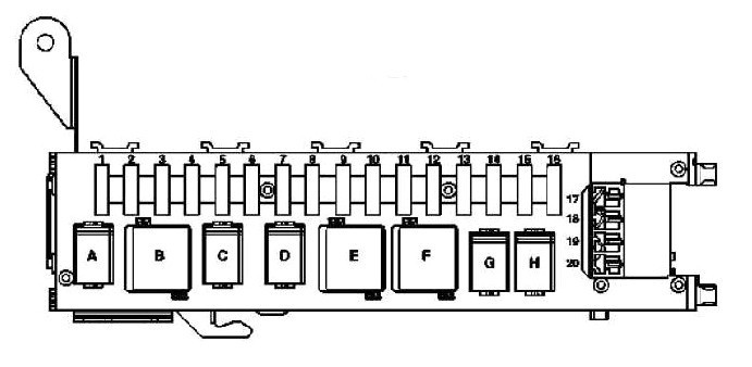
designation
| one | 30A Right front seat adjustment switch block |
| Switch for partially electric adjustment of the front passenger seat | |
| two | 30A Left front seat adjustment switch block |
| Power driver's seat partial adjustment switch | |
| 3 | 7,5 A Interior lighting |
| Trunk lighting | |
| remote control receiver | |
| Tire pressure monitoring | |
| 20A TV tuner | |
| 4 | Fuel pump relay 20A |
| 5 | 20A Engines 112.961 (up to 31.3.04): charge air cooler circulation pump |
| Except 112.961: Spare relay 2 | |
| 6 | Spare fuse 25A |
| 7 | 7,5 A Backup relay 1 |
| eight | Rear window antenna booster module 7,5 A |
| alarm siren | |
| ATA tilt sensor | |
| nine | 25A Upper control panel control unit |
| ten | 40A Heated rear window |
| 11 | Spare fuse 20A |
| 12 | Auxiliary power connector 15 A |
| 203.0 - USA (until 31.03.04/XNUMX/XNUMX): Rose window | |
| thirteen | 5A Air pump for multi-contour seat |
| Voice Control System (VCS) - Voice Control Unit | |
| Motorola Star TAC Cell Phone Upgrade - Portable Cell Phone D2B Interface | |
| Rear Reading Light | |
| Indication of the PTS signal (parktronic) | |
| PTS control unit (parktronic) | |
| 14 | 15A Rear wiper |
| fifteen | 10A Fill relay, receiver polarity |
| sixteen | 20A For VSC: Voice control unit |
| Update for Motorola Star TAC CTEL: D2B interface for mobile phone | |
| 17 | 20A Trailer control unit |
| Eighteen | Drawbar socket 20A, 13 pins |
| nineteen | 20A Air pump for multicontour seat |
| twenty | 15A Dimming rear window |
| 203.2/7 - USA: Rose Window | |
| Relay | |
| AN | Fuel pump relay |
| Б | Relay 2, terminal 15R |
| С | Backup relay 2 |
| Д | Backup relay 1 |
| Me | Rear heater relay |
| Ф | Relay 1, terminal 15R |
| GRAM | Fill relay, polarity switch 1 |
| TIME | Fill relay, polarity switch 2 |
There is something to supplement the material - write in the comments.
5 comments
M goofs
Where is the relay for the sliding tilt roof?
Mladen Bečić
Great site. Excellent orientation aid for this car.
611.962w203.004
Finally a pattern done really well
David
Hello
Very very good
Thank you very much
How to record all of this
Azzedine
it's really interesting I would like to record