mobile dwucylindrowiec
This is an interesting model powered by compressed air, made from cheap recycled materials or the workshop's own materials. A wire connecting rod, a working gas distribution mechanism, a rotating flywheel make the mobile look like a working steam engine. To become the owner of such a toy, it is best to get to work right away.
Our working model has two diaphragm cylinders, cranks, a connecting rod and a timing mechanism. Unfortunately, although it is similar in principle to a steam engine, we cannot power it with steam. The mobile will be driven by compressed air. First, at the first attempts to start compressed air source our lungs can be. An accurately and correctly made model is not too demanding, and breathing exercises in the era of coronovirus can be beneficial for our health. But remember not to overdo it. It is best if there is a compressor in the workshop, and if not, then you can use a regular cylinder, which will be a temporary reservoir of compressed air.
Materials needed for construction: three large caps from 5-liter water bottles, a silicone glove or two balloons, rubber bands, two plastic cocktail straws, thin boards from exotic fruit boxes, an old and expired ATM card (check if it is expired) or something similar fidelity, but made of thick plastic, a metal nut from a standard flywheel jar, a wire hanger or other thin wire, for example 2 mm in diameter, two M3 screws with washers and nuts, a needle tube.
Tools: a screwdriver that works like a drill, a 2 or 3 mm drill bit depending on the diameter of the wire, a 4 mm drill bit, a hacksaw blade or a dremel with a wood cutting disc, hot glue in a batch gun, a knife with breakable blades, scissors, a felt-tip pen, pliers, a typesetting square or joiner's square.
4. Bottom bracket of the model and back and front panels of the case
5. Crankshaft bearings
membrane cylinder. It is made from large walnut. Drill a hole 4 mm in diameter in the bottom in the center to fit a cocktail tube. We need two of these cylinders.
Membranes. Cylinders have diaphragms instead of pistons. The material for their manufacture will be the cut off top of the balloon or a silicone or thin rubber glove. It must be new for security reasons. We cut rubber discs of a suitable size, i.e. about 70 millimeters in diameter. We make a hole in the middle of the membrane, into which we fasten the M3 screw with washers and nuts. Attach a piece of silicone rubber to the side of the cylinder with a rubber band folded several times around the circumference of the cap. We can also attach it with a tie, which we will shorten accordingly. Make sure the bolts protruding from the top are more or less in the center of the nut. Use scissors to cut off any excess rubber that is flush with the bottom of the cap.
Figure 1. The crankshaft and the last crank are rotated 90 degrees to the rest.
Connecting rod. We will bend it with wire pliers from the hanger. Such wire is thick and difficult to bend, and we must harden it first. To do this, let it brown in the flame of a gas burner or lamp solder and let it cool slowly. It will no longer spring back, and it can be easily shaped with pliers according to the drawn diagram. Please note that the cylinder cranks operate in the same plane, and the timing crank is at an angle of 90 degrees to them. We can see it in the picture.
Corps. We cut off two cocktail plastic tubes 90 millimeters long. At the end of each tube we drill a hole with a diameter of 2 millimeters, i.e. the same as your wire. We will choose the length of the connecting rods later when assembling the model.
Figure 2. Synchronization principle
Distribution. Here we need thick plastic. This may be an expired ATM card that should be destroyed. If we don’t have it, we can use other plastic with similar parameters, for example, from loyalty cards that stores are so willing to give out. The timing of the machine has the shape of a flat space in which the slider works freely. The lower part of the timing, the base is a rectangle measuring 45 × 30 millimeters. We drill two holes in it at such a distance from each other, as the circle marks the end of the crankshaft. In our model, this distance is 15 millimeters. It is best to measure it in practice by turning the crankshaft already bent 180 degrees. Through these holes, air will flow through the tubes once into the other cylinder. Glue strips of plastic 4 mm wide to the base of the timing on the sides. These are slider guides. The upper part of the timing cover also has dimensions of 45 × 30 millimeters. In the axis of symmetry of this rectangle, we drill one hole with a diameter of 4 millimeters. Compressed air will be supplied through this hole through a plastic needle. The synchronization operation can be seen in the figure. The supplied air is marked in red, the new compressed air is marked in green, the used and the outlet path.
6. Crankshaft and one of the plastic connecting rods
7. Tubes for supplying air to the cylinders
Zipper. It has the same shape as in the photo. It will work inside the distribution mechanism, relying on the side rails. An elliptical hole measuring 4 x 6 millimeters is drilled into the slide. We drill it with a drill 4 and slightly drill along the axis, holding the material in the pliers. When we place the slider on the timing base, the elliptical hole must align with one of the holes in the base and the other hole in the base must be open. This is where the used air will exit the cylinder. After moving in the other direction, the situation will be reversed and the elliptical shape will be closed by a second hole through which air will be supplied, and the remaining hole through which exhaust air will exit will be exposed. When we theoretically check the operation of our runner, we can glue the timing cover to the guides of the runner. We see it in the photo.
8. These elements must be well glued
9. Slider elements as templates for now
Slider hitch with crankshaft. It is made of a strip of thick plastic, shaped as shown in the photo. Drill a 2mm hole in the top. It will be glued to the slider handle in the area that will come out when you assemble the model.
10. Timing and slider next to the front slider cover
11. Connecting the slider handle to the slider crank
Machine base. It is made from a board measuring 110 by 60 millimeters. We can get thin plywood from disassembled boxes that contain exotic fruits. In the places visible in the photo, we drill or cut holes where the cylinders will be glued.
crankshaft support we will make a bar in the form as in the photo. The height of the carriage is 100 millimeters, the base is approximately 30 millimeters, and the top is 20 millimeters.
12. Drilling a hole in the top of the crank.
13. Additional zipper faceplate with glued plastic tube
Connecting rod bearings. They are plastic rectangles with a drilled hole with a diameter of 2 mm. We need two identical items. Rectangles glued to the bottom bracket of the connecting rod will hold the connecting rod at the correct height and at the same time will be its supports.
Flywheel. It is made from a large metal can lid and two smaller plastic ones. These nuts will make it easier to mount the flywheel perpendicular to the shaft. We drill holes in the center of the nuts with a diameter of 2 mm. Let's try to carefully mark them exactly in the middle, otherwise the wheel will spin unevenly or hang sideways. The places where we have accurately determined the center must be hammered in advance. A drill placed over a groove will not slip. For assembly, it is good to use a board with a hole perpendicular to the surface of the flywheel. Then the plastic nuts will immediately find their correct position in relation to the large metal one.
14. Installing the flywheel on the connecting rod
15. Plastic crankshaft bearings.
Base sides of our engine, in fact, we cut out the front and back from the board. Their dimensions are 110 × 30 millimeters.
Tubes connecting the timing to the cylinders. Their task is to supply compressed air alternately from one cylinder to another. Let's start by cutting out a 30x20mm hard plastic rectangle. This rectangle will be glued to the bottom of the timing base. We drill holes in it exactly along the line of the holes in the timing base. Now carefully select the lengths of the two cocktail tubes. Let's try how long and where the knees should be so that you can easily connect the timing to the cylinders. We see it in the photo. The most difficult element of our work is gluing the plate with tubes to the base of the timing so that the holes are not clogged with glue and that they do not merge into one whole, because the model will not want to work. This is perhaps the most difficult point in our work. When this is overcome, it remains only to insert the tubes into the holes in the cylinders and cover these places tightly with hot glue. I want to remind you that glue can be formed with a still warm wet finger.
16. Mounting bearings and cranks on the crankshaft
17. Mounting the slider crank on the crankshaft
Installation of cylinders. Let's start by attaching the screws to the membranes. Make a small hole in the rubber disk intended for the membrane. We put a bolt with a washer. We will make sure that in the future the air does not escape through an opening that is too large. We assemble the crank holders in the following order: bolt, washer, diaphragm washer and nut. Now we put the diaphragm on the surface of the cylinder nut. Use a tight elastic band to attach the membrane to the side of the cap. We can achieve a similar effect by securing the membrane with a tripod.
18. A compressed air supply tube is glued to the slider
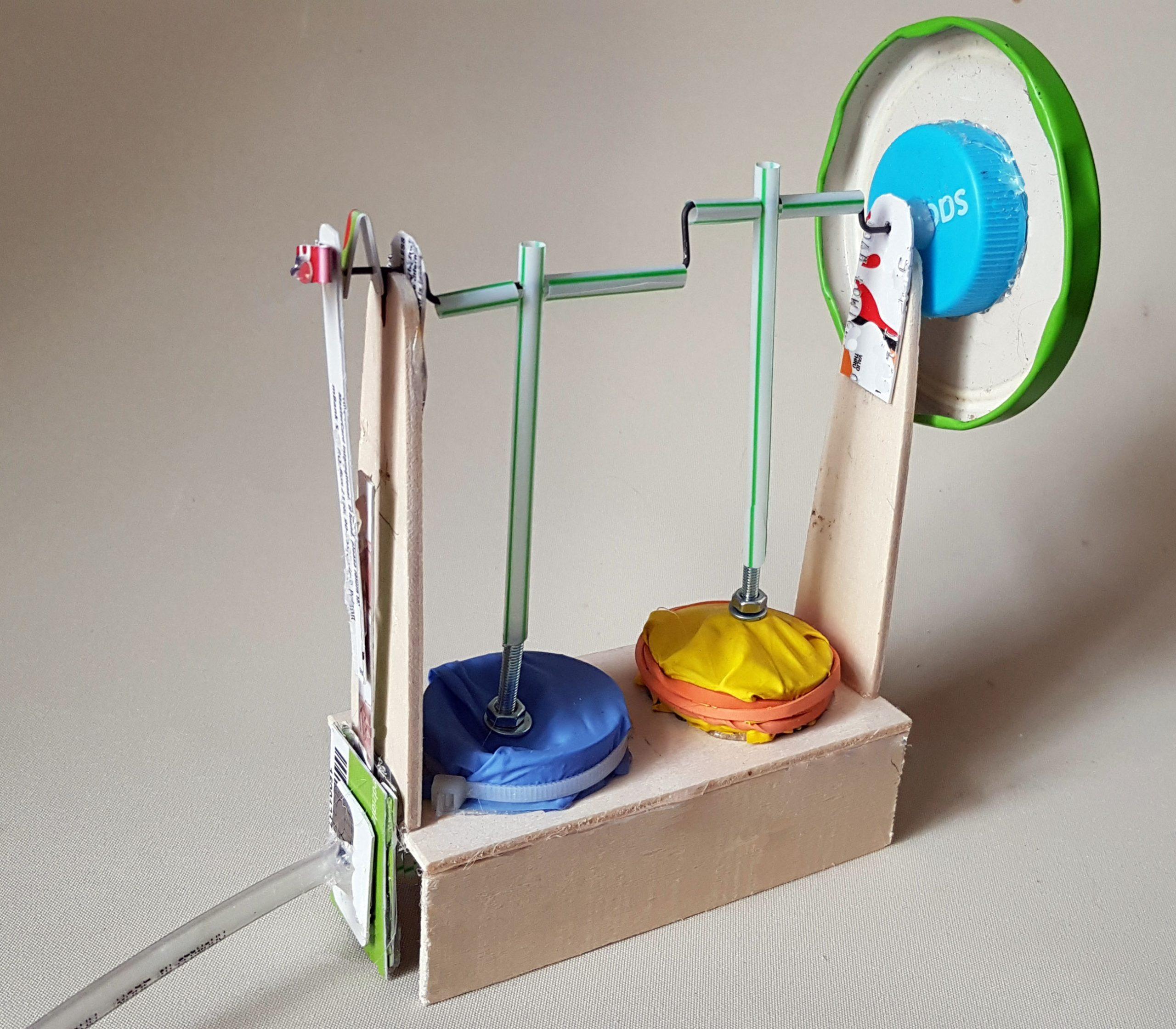
19. Model ready to go
Base models. Glue both cylinders to the top of the wooden base using hot glue. Glue the board rectangles to the front and back of the base. Glue the crankshaft bearings to the top surface of the base on the sides.
Flywheel put on the crankshaft and fix it with hot glue on both sides. Before this, we will move the bearing of the connecting rod mounting shaft, i.e. rectangle with a hole.
Connecting rod cranks. Slide the plastic grips onto the connecting rod shaft. Each crank must pass through its own cylinder. To prevent the cranks from wandering along the shaft of cocktail pipes cut in half along their length, we will make spacers of the appropriate length. We see them in the photo.
Crankshaft mount. Glue plastic bearings to the wooden crankshaft bearings, i.e. flat pieces of plastic with holes, as shown in the photo. Check if the shaft rotates correctly. Connecting the cylinders to the crankshaft. Using hot glue, we connect the shaft cranks with the bolts embedded in the membranes. Let's do this carefully, because cocktail straws are sensitive to heat. We connect the holes in the cylinders with plastic pipes to the timing holes.
Model power supply. We attach a plastic mattress to the front of the timing belt with hot glue, with which we will supply air to our engine. We can use our own lungs, but it's better to use a workshop compressor. When compressed air is supplied, the membrane cylinders will be filled with it and the flywheel will begin to rotate.
A game. If we did everything exactly and the air enters the cylinders through the timing, then these alternately move the crankshaft and our mobile works. Have fun.
See also: