Pressure tank - rail, pressure regulator, crankshaft and camshaft pressure and temperature sensor
Content
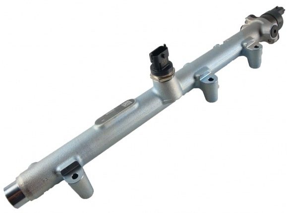
High pressure fuel tank (rail - injection distributor - rail)
It acts as a high pressure fuel accumulator and at the same time dampens pressure fluctuations (fluctuations) that occur when the high pressure pump pulsates fuel and constantly opens and closes the injectors. Therefore, it must have sufficient volume to limit these fluctuations, on the other hand, this volume should not be too large in order to quickly create the necessary constant pressure after starting for trouble-free starting and operation of the engine. Simulation calculations are used to optimize the resulting volume. The volume of fuel injected into the cylinders is constantly replenished into the rail due to the supply of fuel from the high pressure pump. The high pressure fuel compressibility is used to achieve the storage effect. If more fuel is then pumped out of the rail, the pressure remains almost constant.
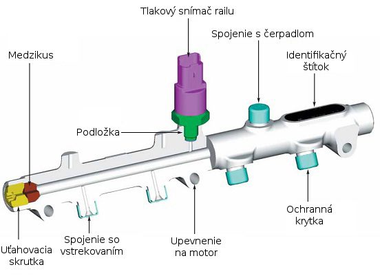
Another task of the pressure tank - rails - is to supply fuel to the injectors of individual cylinders. The design of the tank is the result of a compromise between two conflicting requirements: it has an elongated shape (spherical or tubular) in accordance with the design of the engine and its location. According to the production method, we can divide the tanks into two groups: forged and laser welded. Their design should allow the installation of a rail pressure sensor and a limiting acc. pressure control valve. The control valve regulates the pressure to the required value, and the restrictive valve limits the pressure only to the maximum allowable value. Compressed fuel is supplied through the high pressure line through the inlet. It is then distributed from the reservoir to the nozzles, with each nozzle having its own guide.
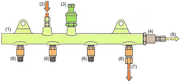
1 - high pressure tank (rail), 2 - power supply from the high pressure pump, 3 - fuel pressure sensor, 4 - safety valve, 5 - fuel return, 6 - flow restrictor, 7 - pipeline to injectors.
Pressure relief valve
As the name suggests, the pressure relief valve limits the pressure to the maximum allowable value. The restrictor valve works exclusively on a mechanical basis. It has an opening on the side of the rail connection, which is closed by the tapered end of the piston in the seat. At operating pressure, the piston is pressed into the seat by a spring. When the maximum fuel pressure is exceeded, the spring force is exceeded and the piston is pushed out of the seat. Thus, excess fuel flows through the flow holes back to the manifold and on to the fuel tank. This protects the device from destruction due to the large pressure rise in the event of a malfunction. In the latest versions of the restrictor valve, an emergency function is integrated, thanks to which a minimum pressure is maintained even in the event of an open drain hole, and the vehicle can move with restrictions.
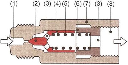
1 - supply channel, 2 - cone valve, 3 - flow holes, 4 - piston, 5 - compression spring, 6 - stop, 7 - valve body, 8 - fuel return.
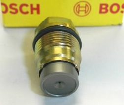
Flow restrictor
This component is mounted on the pressure tank and the fuel flows through it to the injectors. Each nozzle has its own flow restrictor. The purpose of the flow restrictor is to prevent fuel leakage in the event of an injector failure. This is the case if the fuel consumption of one of the injectors exceeds the maximum allowable amount set by the manufacturer. Structurally, the flow limiter consists of a metal body with two threads, one for mounting on the tank, and the other for screwing the high pressure pipe to the nozzles. The piston located inside is pressed against the fuel tank by a spring. She tries her best to keep the channel open. During the operation of the injector, the pressure drops, which moves the piston towards the outlet, but it does not close completely. When the nozzle works properly, the pressure drop occurs in a short time, and the spring returns the piston to its original position. In the event of a malfunction, when the fuel consumption exceeds the set value, the pressure drop continues until it exceeds the spring force. Then the piston rests against the seat on the outlet side and remains in this position until the engine stops. This shuts off the fuel supply to the failed injector and prevents uncontrolled fuel leakage into the combustion chamber. However, the fuel flow limiter also operates in the event of a malfunction when there is only a slight leakage of fuel. At this time, the piston returns, but not to its original position and after a certain time - the number of injections reaches the saddle and stops the fuel supply to the damaged nozzle until the engine turns off.
1 - rack connection, 2 - locking insert, 3 - piston, 4 - compression spring, 5 - housing, 6 - connection with injectors.
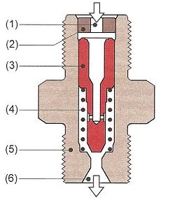
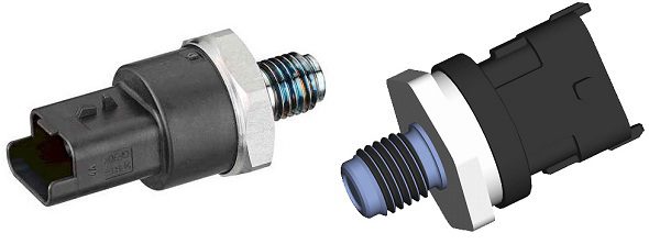
Fuel pressure sensor
The pressure sensor is used by the engine control unit to accurately determine the instantaneous pressure in the fuel tank. Based on the value of the measured pressure, the sensor generates a voltage signal, which is then evaluated by the control unit. The most important part of the sensor is the diaphragm, which is located at the end of the supply channel and is pressed against by the supplied fuel. The semiconductor element is placed on the membrane as a sensing element. The sensing element contains elastic resistors steamed on the diaphragm in a bridge connection. The measuring range is determined by the thickness of the diaphragm (the thicker the diaphragm, the higher the pressure). Applying pressure to the membrane will cause it to bend (approximately 20-50 micrometers at 150 MPa) and thus change the resistance of the elastic resistors. When the resistance changes, the voltage in the circuit changes from 0 to 70 mV. This voltage is then amplified in the evaluation circuit to a range of 0,5 to 4,8 V. The supply voltage of the sensor is 5 V. In short, this element converts the deformation into an electrical signal, which is modified - amplified and from there goes to the control unit for evaluation, where the fuel pressure is calculated using the stored curve. In case of deviation, it is regulated by a pressure control valve. The pressure is almost constant and independent of load and speed.
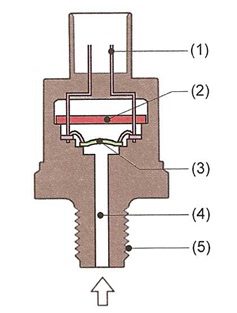
1 - electrical connection, 2 - evaluation circuit, 3 - diaphragm with sensing element, 4 - high pressure fitting, 5 - mounting thread.
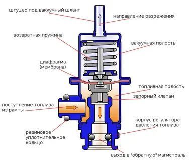
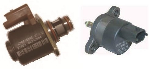
Fuel pressure regulator - control valve
As already mentioned, it is necessary to maintain a practically constant pressure in the pressurized fuel tank, regardless of load, engine speed, etc. The function of the regulator is that if lower fuel pressure is required, the ball valve in the regulator opens and excess fuel is directed return line to the fuel tank. Conversely, if the pressure in the fuel tank drops, the valve closes and the pump builds up the required fuel pressure. The fuel pressure regulator is located either on the injection pump or on the fuel tank. The control valve operates in two modes, the valve is on or off. In the inactive mode, the solenoid is not energized and thus the solenoid has no effect. The valve ball is pressed into the seat only by the force of the spring, the stiffness of which corresponds to a pressure of about 10 MPa, which is the opening pressure of the fuel. If an electric voltage is applied to the electromagnet coil - current, it begins to act on the armature together with the spring and closes the valve due to pressure on the ball. The valve closes until a balance is reached between the fuel pressure forces on the one hand and the solenoid and spring on the other. It then opens and maintains a constant pressure at the desired level. The control unit responds to pressure changes caused, on the one hand, by the fluctuating amount of fuel supplied and the withdrawal of the nozzles, by opening the control valve in different ways. To change the pressure, less or more current flows through the solenoid (its action either increases or decreases), and thus the ball is more or less pushed into the valve seat. The first generation common rail used the pressure regulating valve DRV1, the second and third generations the DRV2 or DRV3 valve is installed together with the metering device. Thanks to the two-stage regulation, there is less heating of the fuel, which does not require additional cooling in the additional fuel cooler.
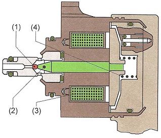
1 - ball valve, 2 - solenoid armature, 3 - solenoid, 4 - spring.
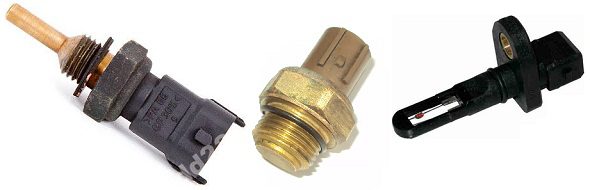
Temperature sensors
Temperature sensors are used to measure engine temperature based on coolant temperature, intake manifold charge air temperature, engine oil temperature in the lubrication circuit, and fuel temperature in the fuel line. The measuring principle of these sensors is a change in electrical resistance caused by a rise in temperature. Their supply voltage of 5 V is changed by changing the resistance, then converted in a digital converter from an analog signal to a digital signal. Then this signal is sent to the control unit, which calculates the appropriate temperature in accordance with a given characteristic.
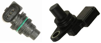
Crankshaft position and speed sensor
This sensor detects the exact position and the resulting engine speed per minute. It is an inductive Hall sensor that is located on the crankshaft. The sensor sends an electrical signal to the control unit, which evaluates this value of the electrical voltage, for example, to start (or end) fuel injection, etc. If the sensor does not work, the engine will not start.
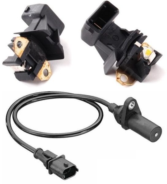
Camshaft position and speed sensor
The camshaft speed sensor is functionally similar to the crankshaft speed sensor and is used to determine which piston is at top dead center. This fact is needed to determine the exact ignition timing for gasoline engines. In addition, it is used to diagnose timing belt slippage or chain skipping and when starting the engine, when the engine control unit determines using this sensor how the entire crank-coupling-piston mechanism actually rotates at the beginning. In the case of engines with VVT, a variable valve timing system is used to diagnose the operation of the variator. The engine can exist without this sensor, but a crankshaft speed sensor is required, and then the camshaft and crankshaft speed are divided in a ratio of 1: 2. In the case of a diesel engine, this sensor only plays an initiating role at start-up, telling the ECU (control unit), which piston is first at top dead center (which piston is on the compression or exhaust stroke when moving to top dead center). center). This may not be obvious from the crankshaft position sensor at start-up, but while the engine is running, the information received from this sensor is already quite enough. Thanks to this, the diesel engine still knows the position of the pistons and their stroke, even if the sensor on the camshaft fails. If this sensor fails, the vehicle will not start or will take longer to start. As in the case of a failure of the sensor on the crankshaft, here the engine control warning lamp on the instrument panel lights up. Usually the so-called Hall sensor.