Fuel injection timing advance
Content
The most important criteria for optimizing the operation of a diesel engine are:
- low toxicity of exhaust gases;
- low noise level of the combustion process;
- low specific fuel consumption.
The moment when the injection pump begins to supply fuel is called the start of supply (or closing of the channel). This point in time is selected according to the power-on delay period (or simply the power-on delay). These are variable parameters that depend on the specific mode of operation. The injection delay period is defined as the period between the start of supply and the start of injection, and the ignition delay period is defined as the period between the start of injection and the start of combustion. The start of injection is defined as the angle of rotation of the crankshaft in the TDC region at which the injector injects fuel into the combustion chamber.
The onset of combustion is defined as the ignition time of the air/fuel mixture, which can be affected by the onset of injection. In high-pressure fuel pumps, it is best to adjust the start of supply (closing of the channel) depending on the number of revolutions using an injection advance device.
Purpose of injection advance device
Since the injection advance device directly changes the injection start time, it can be defined as the injection start controller. An eccentric-type injection advance device (also called an injection advance clutch) converts the engine torque supplied to the injection pump, while performing its regulating functions. The torque required by the injection pump depends on the size of the injection pump, the number of piston pairs, the amount of fuel injected, injection pressure, plunger diameter and cam shape. The fact that engine torque has a direct effect on injection timing characteristics must be considered in the design along with potential power output.
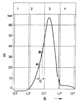
Cylinder pressure
Rice. Tank pressure: A. Start of injection; B. The beginning of burning; C. Ignition delay. 1. Introductory race; 2. Compression stroke; 3. Labor career; 4. Release the run OT-TDC, UT-NMT; 5. Pressure in the cylinder, bar; 6. Piston position.
The design of the injection advance device
The injection advance device for the in-line injection pump is mounted directly on the end of the injection pump camshaft. There is a fundamental difference between open and closed type injection advance devices.
The closed type injection advance device has its own lubricating oil reservoir, which makes the device independent of the engine lubrication system. The open design is directly connected to the engine lubrication system. The body of the device is attached to the gearbox with screws, and the compensating and adjusting eccentrics are installed in the body so that they rotate freely. The compensation and adjustment eccentric is guided by a pin rigidly connected to the body. In addition to being cheaper, the "open" type has the advantage of requiring less space and lubricates more efficiently.
The principle of operation of the injection advance device
The injection advance device is driven by a gear train that is installed in the engine timing case. The connection between the input and output for the drive (hub) is made through pairs of interlocking eccentric elements.
The largest of them, the adjusting eccentrics (4), are located in the holes of the stop disc (8), which in turn is screwed to the drive element (1). The compensating eccentric elements (5) are mounted on the adjusting eccentrics (4) and guided by them and the bolt on the hubs (6). On the other hand, the hub bolt is directly connected to the hub (2). The weights (7) are connected to the adjusting eccentric and are held in their original position by springs of variable stiffness.
Rice a) in the starting position; b) low speed; c) average turnovers; d) high speed end position; a is the injection advance angle.
Injection advance device dimensions
The size of the injection advance device, determined by the outer diameter and depth, in turn determines the mass of the installed weights, the distance between the centers of gravity and the possible path of the weights. These three factors also determine the power output and application.
M size injection pump
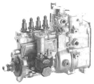
Rice. M size injection pump
Rice. 1. Safety valve; 2. Sleeve; 7 camshaft; 8. Kam.
The M-size injection pump is the smallest pump in the line of in-line injection pumps. It has a light alloy body and is flange-mounted to the engine. Access to the inside of the pump is possible after removal of the base plate and side cover, so a size M pump is defined as an open injection pump. The maximum injection pressure is limited to 400 bar.
After removing the side cover of the pump, the amount of fuel supplied by the plunger pairs can be adjusted and set at the same level. Individual adjustment is carried out by moving the clamping parts on the control rod (4).
During operation, the installation of the pump plungers and, together with them, the amount of fuel supplied is regulated by the control rod within the limits determined by the design of the pump. The M-size injection pump rod is a round steel rod with a flat, on which slotted fasteners (5) are installed. The levers (3) are rigidly connected to each control sleeve, and the riveted rod at its end enters the groove of the control rod holder. This design is known as lever control.
The injection pump plungers are in direct contact with the roller tappets (6), and the stroke is preliminarily adjusted by selecting rollers of a suitable diameter for the tappet.
The lubrication of the injection pump of size M is carried out by the usual supply of engine oil. M size injection pumps are available with 4,5 or 6 piston pairs (4-, 5- or 6-cylinder injection pumps) and are designed for diesel fuel only.
Injection pump size A
Rice. Size A Injection Pump
In-line A-frame injection pumps with a wide delivery range directly follow the M-frame injection pump. This pump also has a light alloy casing and can be mounted on a motor with a flange or a frame. Type A injection pump also has an “open” design, and the injection pump liners (2) are inserted directly from above into the aluminum housing, while the wastegate assembly (1) is pressed into the injection pump casing using a valve holder. Seal pressure, which is much higher than the hydraulic supply pressure, must be absorbed by the injection pump housing. For this reason, the maximum injection pressure is limited to 600 bar.
Unlike the M type injection pump, the A type injection pump is equipped with an adjusting screw (with lock nut) (7) on each roller follower (8) to adjust the prestroke.
To adjust the amount of fuel supplied by the control rail (4), the A-type injection pump, unlike the M-type injection pump, is equipped with gear control, and not lever control. The toothed segment fixed on the control sleeve (5) of the plunger engages with the control rack and in order to adjust the pairs of plungers to the same lead, it is necessary to loosen the set screws and turn the control sleeve clockwise relative to the toothed segment and thus relative to the control rail.
All work on adjusting this type of injection pump must be carried out with the pump mounted on a support and with an open casing. Like the M injection pump, the Type A injection pump has a spring-loaded side cover that must be removed to gain access to the inside of the injection pump.
For lubrication, the injection pump is connected to the engine lubrication system. The A-type injection pump is available in versions up to 12 cylinders and, unlike the M-type injection pump, is suitable for operation with various types of fuel (not only diesel).
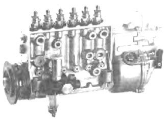
WM size injection pump
Rice. HPFP size WM
The in-line MW injection pump has been designed to meet the higher pressure requirement. The MW injection pump is a closed type in-line injection pump with a maximum injection pressure limited to 900 bar. It also has a light alloy body and is attached to the engine with a frame, flat base or flange.
The design of the MW injection pump differs markedly from the design of the A and M injection pumps. The main difference is the use of a pair of plungers, including a bushing (3), a discharge valve and a discharge valve holder. It is installed outside the engine and is inserted from above into the injection pump housing. On the MW injection pump, the pressure valve holder is screwed directly into the bushing protruding upwards. The pre-stroke is controlled by shims that are inserted between the body and the sleeve with the valve assembly. Adjustment of the uniform supply of individual plunger pairs is carried out outside the injection pump by turning the plunger pairs. The piston pair mounting flanges (1) are provided with slots for this purpose.
Rice. 1. Flange for fastening a pair of plungers; 2. Safety valve; 3. Sleeve; 4. Plunger; 5. Control rail; 6. Control sleeve; 7. Roller pusher; 8 camshaft; 9. Kam.
The position of the injection pump plunger remains unchanged when the sleeve assembly with the discharge valve (2) is rotated. The MW injection pump is available in versions with 8 sleeves (8 cylinders) and is suitable for various mounting methods. It runs on diesel fuel and is lubricated through the engine's lubrication system.
P-size injection pump
Rice. P-size injection pump
Rice. 1. Safety valve; 2. Sleeve; 3. Traction control; 4. Control sleeve; 5. Roller pusher; 6 camshaft; 7. Camera.
The P size (type) in-line injection pump has also been designed to provide a high maximum injection pressure. Like the MW injection pump, this is a closed type pump that is attached to the engine with a base or flange. In the case of P-type injection pumps, designed for a peak injection pressure of 850 bar, the sleeve (2) is inserted into the flange sleeve, which is already threaded for the discharge valve holder (1). With this version of the sleeve installation, the sealing force does not load the pump casing. The pre-stroke is set in the same way as for the MW injection pump.
In-line high pressure fuel pumps designed for low injection pressure use conventional filling of the fuel line. In this case, the fuel passes through the fuel lines of the individual bushings one after the other and in the direction of the longitudinal axis of the injection pump. Fuel enters the line and exits through the fuel return system.
Taking the P8000 version P injection pump as an example, which is rated for injection pressures up to 1150 bar (injection pump side), this filling method can cause an excessive fuel temperature difference (up to 40 °C) inside the injection pump between the first and last hose. Since the energy density of a fuel decreases as its temperature increases, and therefore as volume increases, this will result in different amounts of energy being injected into the engine's combustion chambers. In this regard, such high-pressure fuel pumps use transverse filling, that is, a method in which the fuel lines of individual hoses are separated from each other by means of throttling holes).
This injection pump is also connected to the engine lubrication system for lubrication. The Type P high pressure fuel pump is also available in versions with up to 12 liners (cylinders) and is suitable for both diesel and other fuels.