Passenger car axles
Content
The axle is the part of the vehicle through which two opposite wheels (right and left) are attached/suspended to the vehicle's supporting structure.
The history of the axle goes back to the days of horse-drawn carriages, from which the axles of the first cars were borrowed. These axles were very simple in design, in fact, the wheels were connected by a shaft that was rotatably attached to the frame without any suspension.
As the demands on cars grew, so did the axles. From simple rigid axles to leaf springs to modern multi-element coil springs or air bellows.
The axles of modern cars are a relatively complex structural system, the task of which is to provide the best driving performance and driving comfort. Since their design is the only thing that connects the car to the road, they also have a big impact on the active safety of the vehicle.
The axle connects the wheels to the chassis frame or the vehicle body itself. It transfers the weight of the vehicle to the wheels, and also transfers the forces of motion, braking and inertia. It provides precise and sufficiently strong guidance of the attached wheels.
The axle is the unsprung part of the car, so the designers try to make the most of it in the production of light alloys. The split axles are made up of separate axle shafts.
Axial division
By design
- Rigid axles.
- Rotary axes.
By function
- Driving axle - the axle of the vehicle, to which the engine torque is transmitted and the wheels of which drive the vehicle.
- Driven (driven) axle - an axle of the vehicle to which the engine torque is not transmitted, and which has only a carrier or steering function.
- A steered axle is an axle that controls the direction of the vehicle.
According to the layout
- Front axle.
- Middle axis.
- Rear axle.
By the design of the wheel supports
- Dependent (fixed) mounting – the wheels are connected transversely by a beam (bridge). Such a rigid axis is kinematically perceived as a single body, and the wheels interact with each other.
- Nindependent wheel alignment - each wheel is suspended separately, the wheels do not directly affect each other when springing.
Wheel fixing function
- Allow the wheel to move vertically relative to the frame or body.
- Transfer forces between the wheel and the frame (body).
- Under all circumstances, ensure that all wheels are in constant contact with the road.
- Eliminate unwanted wheel movements (side shift, roll).
- Enable control.
- Enable braking + seizure of braking force.
- Engage the transmission of torque to the drive wheels.
- Provide a comfortable ride.
Axle design requirements
Different and often conflicting requirements are imposed on the axles of vehicles. Automakers have different approaches to these requirements and usually choose a compromise solution.
For example. in the case of lower class cars, the emphasis is on a cheap and simple axle design, while in the case of higher class cars, driving comfort and wheel control are paramount.
In general, axles should limit the transmission of vibrations to the vehicle cab as much as possible, provide the most accurate steering and wheel-to-road contact, production and operating costs are important, and the axle should not unnecessarily restrict the luggage compartment. space for the crew or engine of the vehicle.
- Rigidity and kinematic precision.
- Minimal geometry change during suspension.
- Minimal tire wear.
- Long life.
- Minimum dimensions and weight.
- Resistance to aggressive environments.
- Low operating and production costs.
Axle parts
- Tire.
- Disk wheels.
- Hub bearing.
- Wheel suspension.
- Suspended storage.
- Suspense.
- Damping.
- Stabilization.
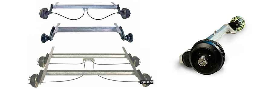
Dependent wheel suspension
Rigid axis
Structurally, it is a very simple (no pins and hinges) and cheap bridge. The type belongs to the so-called dependent suspension. Both wheels are rigidly connected to each other, the tire is in contact with the road over the entire width of the tread, and the suspension does not change the wheelbase or relative position. Thus, the relative position of the axle wheels is fixed in any road situation. However, in the case of a one-way suspension, the deflection of both wheels towards the road changes.
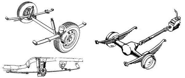
The rigid axle is driven by leaf springs or coil springs. The leaf springs are attached directly to the body or frame of the vehicle and, in addition to the suspension, they also provide steering control. In the case of coil springs, it is necessary to use additional transverse as well as longitudinal guides, since they do not transmit practically any lateral (longitudinal) forces, unlike leaf springs.
Due to the high rigidity of the entire axle, it is still used in real SUVs as well as commercial vehicles (consumables, pickup trucks). Another advantage is tire contact with the road over the entire tread width and a constant wheel track.
The disadvantages of a rigid axle include a large unsprung mass, which includes the weight of the axle of the axle, transmission (in the case of a driven axle), wheels, brakes and, in part, the weight of the connecting shaft, guide levers, springs. and damping elements. The result is reduced comfort on uneven surfaces and reduced driving performance when driving faster. The wheel guide is also less accurate than with independent suspension.
Another disadvantage is the high space requirement for axle movement (suspension), which results in a taller structure as well as a higher center of gravity of the vehicle. In the case of drive axles, the shocks are transmitted to the rotating parts that are part of the axle.
The rigid axle can be used as a front-wheel drive, as well as a driving axle or both a rear driving and a driving axle.
Rigid axle design
Simple bridge axle suspended from leaf springs
- Simple construction.
- The spring accepts longitudinal and lateral stresses (for large springs).
- Large internal damping (friction).
- Simple installation.
- High lifting capacity.
- Large weight and length of the spring.
- Low running costs.
- Complex loads during transient modes of vehicle operation.
- During suspension, the axle axle is twisted.
- For a comfortable ride, a low spring rate is required - you need long leaf springs + lateral flexibility and lateral stabilization.
- To relieve tensile stresses during braking and acceleration, the leaf spring can be supplemented with longitudinal rods.
- The leaf springs are supplemented with shock absorbers.
- For progressive characteristics of the spring, it is supplemented with additional blades (step change in stiffness at high load) - bogies.
- This type of axle is rarely used for the suspension of passenger cars and light commercial vehicles.
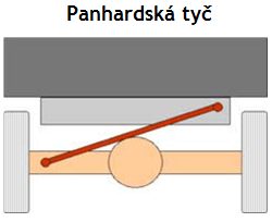
Panara Barbell
To improve the driving performance and stability of the car, it is necessary that the rigid axle is so-called oriented both in the transverse and longitudinal directions.
Nowadays, the more commonly used coil springs are replacing the previously used leaf springs, whose important function, in addition to springing, was also the direction of the axle. However, coil springs do not have this function (they transmit almost no directional forces).
In the transverse direction, Panhard rod or Watt's line is used to guide the axis.
In the case of a Panhard rod, it is the wishbone connecting the axle axle to the frame or body of the vehicle. The disadvantage of this design is the lateral displacement of the axle relative to the vehicle during suspension, which leads to a deterioration in driving comfort. This disadvantage can be largely eliminated by the longest possible design and, if possible, horizontal mounting of the Panhard rod.
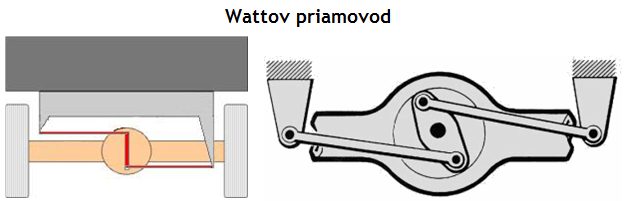
Watt line
The watt line is the mechanism used to cross the rear rigid axle. It is named after its inventor James Watt.
The upper and lower arms must be the same length and the axle axle moves perpendicular to the road. When steering a rigid axle, the center of the hinge element of the guide is mounted on the axle axle and is connected by levers to the body or frame of the vehicle.
This connection provides a rigid lateral direction of the axle, while eliminating the lateral movement that occurs in the case of suspension when using a Panhard rod.
Longitudinal axis guide
Watt's line and Panhard's thrust stabilize the axle in the lateral direction only, and additional guidance is required to transfer the longitudinal forces. For this, simple trailing arms are used. In practice, the following solutions are most often used:
- A pair of trailing arms is the simplest type, essentially replacing the lamellar lip guide.
- Four trailing arms - unlike a pair of arms, in this design, the parallelism of the axis is maintained during suspension. However, the disadvantage is slightly more weight and a more complex design.
- The third option is to drive the axle with two longitudinal and two inclined levers. In this case, the other pair of tilting arms also allows the absorption of lateral forces, thus eliminating the need for additional lateral guidance through the Panhard bar or Watt's straight line.
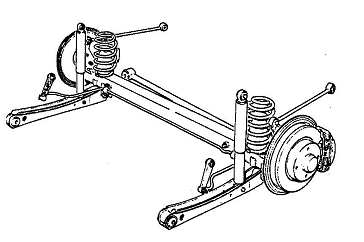
Rigid axle with 1 transverse and 4 trailing arms
- 4 trailing arms guide the axle longitudinally.
- The wishbone (Panhard rod) stabilizes the axle laterally.
- The system is kinematically designed for the use of ball joints and rubber bearings.
- When the upper links are positioned behind the axle, the links are subjected to tensile stress during braking.
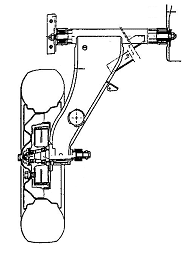
De-Dion rigid axle
This axle was first used by Count De Dion in 1896 and has since been used as a rear axle in passenger cars and sports cars.
This axle assumes some of the properties of a rigid axle, in particular rigidity and a secure connection of the axle wheels. The wheels are connected by a rigid bridge that is guided by a straight Watt line or a Panhard bar that absorbs lateral forces. The axle longitudinal guide is fixed by a pair of tilt levers. Unlike a rigid axle, the transmission is mounted on the body or frame of the vehicle, and the torque is transmitted to the wheels using variable-length PTO shafts.
Thanks to this design, the unsprung weight is significantly reduced. With this type of axle, disc brakes can be placed directly on the transmission, further reducing unsprung weight. Currently, this type of medicine is no longer used, the opportunity to see it, for example, on the Alfa Romeo 75.
- Reduces the size of the unsprung masses of the driving rigid axle.
- The gearbox + differential (brakes) are mounted on the body.
- Only a slight improvement in driving comfort compared to a rigid axle.
- The solution is more expensive than other methods.
- Lateral and longitudinal stabilization is carried out using a watt-drive (Panhard rod), a stabilizer (lateral stabilization) and trailing arms (longitudinal stabilization).
- Axial displacement PTO shafts are required.

Independent wheel suspension
- Increased comfort and driving performance.
- Less unsprung weight (transmission and differential are not part of the axle).
- There is enough space between the compartment for storing the engine or other structural elements of the vehicle.
- As a rule, more complex construction, more expensive production.
- Less reliability and faster wear.
- Not suitable for tough terrain.
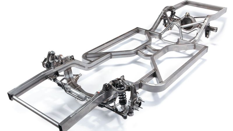
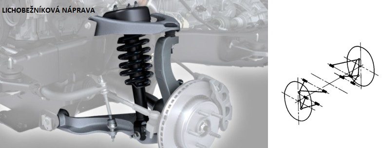
Trapezoidal axis
The trapezoidal axis is formed by upper and lower transverse wishbones, which form a trapezoid when projected into a vertical plane. The arms are attached either to the axle, or to the vehicle frame, or, in some cases, to the transmission.
The lower arm usually has a stronger structure due to the transmission of vertical and a higher proportion of longitudinal / lateral forces. The upper arm is also smaller for spatial reasons, such as the front axle and the location of the transmission.
The levers are housed in rubber bushings, the springs are usually attached to the lower arm. During suspension, wheel deflection, toe, and wheelbase change, which negatively affects the driving characteristics of the vehicle. To eliminate this phenomenon, the optimal design of the temples is important, as well as the correction of the geometry. Therefore, the arms should be placed as parallel as possible so that the tipping point of the wheel is at a greater distance from the wheel.
This solution reduces wheel deflection and wheel replacement during suspension. However, the disadvantage is that the center of the tilt of the axle is offset to the plane of the road, which negatively affects the position of the tilt axis of the vehicle. In practice, the levers are of different lengths, which changes the angle they form when the wheel bounces. It also changes the position of the current tilt point of the wheel and the position of the center of tilt of the axle.
The trapezoidal axle of the correct design and geometry ensures very good wheel guidance and therefore very good driving characteristics of the vehicle. However, the disadvantages are the relatively complex structure and higher manufacturing costs. For this reason, it is currently commonly used in more expensive cars (mid to high end or sports cars).
The trapezoidal axle can be used as a front drive and drive axle or as a rear drive and drive axle.
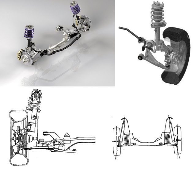
Macpherson Correction
The most commonly used type of axle with independent suspension is the MacPherson (more commonly McPherson), named after designer Earl Steele MacPherson.
The McPherson axle is derived from a trapezoidal axle in which the upper arm is replaced by a sliding rail. Thus, the top is much more compact, which means more space for the drive system or. trunk volume (rear axle). The lower arm is generally triangular in shape and, as with the trapezoidal axle, transfers a large proportion of lateral and longitudinal forces.
In the case of the rear axle, a simpler wishbone is sometimes used which transmits only lateral forces and is complemented by a trailing link, respectively. torsion stabilizer lever for transmission of longitudinal forces. The vertical forces are generated by the damper, which, however, must also be the shear force of the more robust structure due to the load.
On the front steering axle, the damper upper bearing (piston rod) must be rotatable. To prevent the coil spring from twisting during rotation, the upper end of the spring is rotatably supported by a roller bearing. The spring is mounted on the damper housing so that the slideway is not loaded with vertical forces and there is no excessive friction in the bearing under vertical load. However, the increased friction in the bearing is due to the moments of lateral and longitudinal forces during acceleration, braking or steering. This phenomenon is eliminated by a suitable design solution, for example with an inclined spring support, a rubber support for the top support, and a more robust structure.
Another undesirable phenomenon is the tendency for a significant change in wheel deflection during suspension, which leads to a deterioration in driving performance and driving comfort (vibrations, transmission of vibrations to the steering, etc.). For this reason, various improvements and modifications are made to eliminate this phenomenon.
The advantage of the McPherson axle is a simple and inexpensive design with a minimum number of parts. In addition to small and cheap cars, various modifications of McPherson are used in middle-class cars, mainly due to improved design, but also by reducing production costs everywhere.
The McPherson axle can be used as a front drive and drive axle or as a rear drive and drive axle.
Crankshaft
- The crank axle is formed by trailing arms with a transverse swing axis (perpendicular to the longitudinal plane of the vehicle), which are mounted in rubber bearings.
- To minimize the forces acting on the arm support (in particular, reducing the vertical load on the support), vibration and noise transmission to the body, the springs are placed as close as possible to the point of contact of the tire with the ground. ...
- During the suspension, only the wheelbase of the car changes, the deflection of the wheels remains unchanged.
- Low manufacturing and operating costs.
- It takes up little space, and the trunk floor can be placed low - suitable for station wagons and hatchbacks.
- It is mainly used for driving rear axles and very rarely as a driving axle.
- The deflection change is only created when the body is tilted.
- Torsion bars (PSA) are often used for suspension.
- The disadvantage is the significant slope of the curves.
The crank axle can be used as a front driven axle or as a rear driven axle.
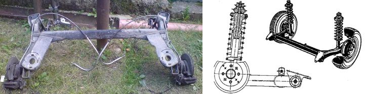
Crankshaft with coupled levers (torsionally flexible crankshaft)
In this type of axle, each wheel is suspended from one trailing arm. The trailing arms are connected by a U-profile, which acts as a lateral stabilizer and absorbs lateral forces at the same time.
A crank axle with connected arms is a semi-rigid axle from a kinematic point of view, because if the cross member were moved to the central axle of the wheels (without trailing arms), then such a suspension would acquire the properties of a rigid axle.
The center of the tilt of the axle is the same as for the normal crank axis, but the center of the tilt of the axle is above the road plane. The axle behaves differently even when the wheels are suspended. With the same suspension of both axle wheels, only the wheelbase of the vehicle changes, but in the case of the opposite suspension or suspension of only one axle wheel, the deflection of the wheels also changes significantly.
The axle is attached to the body with metal-rubber ties. This connection ensures good axle steering when properly designed.
- The shoulders of the crankshaft are connected by a torsionally rigid and torsionally soft rod (mostly U-shaped), which serves as a stabilizer.
- This is the transition between the rigid and longitudinal crankshaft.
- In the case of oncoming suspension, the deflection changes.
- Low manufacturing and operating costs.
- It takes up little space, and the trunk floor can be placed low - suitable for station wagons and hatchbacks.
- Easy assembly and disassembly.
- Light weight of unsprung parts.
- Decent driving performance.
- In the course of the suspension, small changes in toe and track.
- Self-steering understeer.
- Does not allow turning the wheels - use only as a rear drive axle.
- Tendency to oversteer due to lateral forces.
- High shear load on the welds connecting the arms and torsion bar in the opposite spring, which limits the maximum axial load.
- Less stability on uneven surfaces, especially in fast corners.
A crank axle with coupled levers can be used as a rear driven axle.
Pendulum (angular) axis
Also called oblique axis respectively. oblique curtain. The axle is structurally similar to the crank axle, but unlike it has an inclined oscillation axis, which leads to self-steering of the axle during suspension and the effect of understeer on the vehicle.
The wheels are attached to the axle by means of fork levers and metal-rubber supports. During suspension, the track and wheel deflection change minimally. Since the axle does not allow the wheels to rotate, it is only used as the rear (mainly drive) axle. Today it is no longer used, we used to see it in BMW or Opel cars.
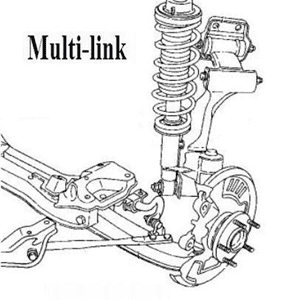
Multi-link axle
This type of axle was used on Nissan's first former flagship, the Maxima QX. Later, the smaller Primera and Almera received the same rear axle.
The multi-link suspension has significantly improved the properties of the transversely mounted torsionally flexible beam on which the structure is based. As such, Multilink uses an inverted U-shaped steel beam to connect the rear wheels, which is very stiff when bending and, on the other hand, relatively flexible when turning. The beam in the longitudinal direction is held by a pair of relatively light guide levers, and at its outer ends it is held vertically by helical springs with shock absorbers, respectively. also with a specially shaped vertical lever at the front.
However, instead of a flexible Panhard beam, usually attached at one end to the body shell and the other to the axle axle, the axle uses a Scott-Russell type multi-link composite element that provides better lateral stability and wheel steering. on the road.
Scott-Russell Mechanism includes a wishbone and control rod. Like the Panhard bar, it also connects the wishbone and torsionally flexible beam to the body. It has a transverse fastening, which allows you to make the trailing arms as thin as possible.
Unlike a Panhard beam, a vehicle's wishbone does not rotate at a fixed point on a torsionally flexible beam. It is fastened with a special case, which is rigid vertically but flexible at the side. A shorter control rod connects the wishbone (approximately midway through its length) and the torsion bar inside the outer housing. When the axis of the torsion beam is raised and lowered relative to the body, the mechanism acts like a Panhard bar.
However, since the wishbone at the end of the torsion beam can move laterally relative to the beam, it prevents the entire axle from moving laterally and at the same time has a lift like a simple Panhard bar.
The rear wheels only move vertically in relation to the body, with no difference between turning to the right or to the left. This connection also allows very little movement between the center of rotation and the center of gravity when the axle is raised or lowered. Even with a longer suspension travel, designed for some models to improve comfort. This ensures that the wheel will be supported even with significant suspension or sharper cornering almost perpendicular to the road, which means that maximum tire-to-road contact is maintained.
The Multilink axle can be used as front-wheel drive, as well as drive axle or rear drive axle.
Multi-link axle - multi-link suspension
- It optimally sets the required kinematic properties of the wheel.
- More precise wheel guidance with minimal wheel geometry changes.
- Driving comfort and vibration damping.
- Low friction bearings in the damping unit.
- Changing the design of one hand without having to change the other hand.
- Light weight and compact – built-up space.
- Has smaller dimensions and weight of the suspension.
- Higher manufacturing costs.
- Shorter service life (especially rubber bearings - silent blocks of the most loaded levers)
The multi-piece axle is based on a trapezoidal axis, but is more demanding in terms of construction and consists of several parts. Consists of simple longitudinal or triangular arms. They are placed either transversely or longitudinally, in some cases also obliquely (in the horizontal and vertical planes).
A complex design - the independence of the levers allows you to very well separate the longitudinal, transverse and vertical forces acting on the wheel. Each arm is set to transmit axial forces only. Longitudinal forces from the road are taken by the leading and leading levers. Transverse forces are perceived by transverse arms of different lengths.
The fine adjustment of the lateral, longitudinal and vertical stiffness also has a positive effect on driving performance and driving comfort. The suspension and often the shock absorber are usually mounted on a support, often transverse, arm. Thus, this arm is subjected to more stress than the others, which means a stronger structure or. different material (eg steel versus aluminum alloy).
To increase the rigidity of the multi-element suspension, the so-called subframe - axle is used. The axle is attached to the body with the help of metal-rubber bushings - silent blocks. Depending on the load of one or another wheel (evasion maneuver, cornering), the toe angle changes slightly.
Shock absorbers are only minimally loaded with lateral stress (and therefore increased friction), so they can be significantly smaller and mounted directly in the coil springs coaxially - to the center. The suspension does not hang in critical situations, which has a positive effect on ride comfort.
Due to higher manufacturing costs, the multi-piece axle is mainly used in mid-range and high-end vehicles, respectively. athletes.
According to car manufacturers, the design of the multi-link axle itself varies greatly. In general, this suspension can be divided into simpler (3-link) and more complex (5 or more levers) mounts.
- In the case of a three-link installation, longitudinal and vertical displacement of the wheel is possible, including rotation around a vertical axis, the so-called 3 degrees of freedom - use with front steering and rear axle.
- With a four-link mounting, vertical wheel movement is allowed, including rotation around a vertical axis, the so-called 2 degrees of freedom - use with front steering and rear axle.
- In the case of a five-link installation, only vertical movement of the wheel is allowed, the so-called 1 degree of freedom - better wheel guiding, use only on the rear axle.