Design features and self-repair of the distributor VAZ 2107
Content
- Interrupter-distributor ignition "seven"
- contact distributor
- Contactless distributor repair
- Contactless distributor
- Octane corrector
Ignition malfunctions of the VAZ 2107, regardless of the type of the system itself (contact or non-contact), are often associated with a breaker-distributor (distributor). Despite its complex electromechanical design, almost any breakdown can be repaired with one's own hands.
Interrupter-distributor ignition "seven"
The distributor is used to generate a pulsed voltage in the low-voltage circuit of the ignition system, as well as to distribute high-voltage pulses to candles. In addition, its functions include automatic adjustment of the spark advance angle.
What distributors are
In the VAZ 2107, depending on the type of ignition system, two types of distributors can be used: contact and non-contact. In appearance, they practically do not differ. The difference between them lies in the device responsible for the formation of a pulse in the low-voltage circuit of the system. For the former, a group of contacts is responsible for this function, for the latter, an electromagnetic sensor, the operation of which is based on the Hall effect. In all other respects, the principle of operation of the devices is identical.
contact distributor
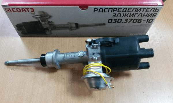
Contact-type distributors were equipped with all models and modifications of the Zhiguli until the beginning of the 90s of the last century. A distributor with serial number 2107 was installed on the VAZ 30.3706.
The design of the contact interrupter-distributor ignition 30.3706
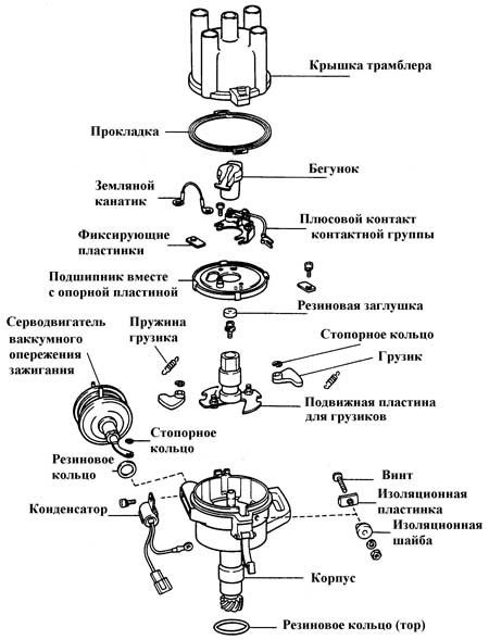
The contact distributor consists of the following elements:
- the body;
- rotor (shaft);
- slider (rotating contact);
- contact breaker;
- capacitor;
- centrifugal and vacuum regulators of the ignition timing;
- cover with main (central) and four side contacts.
 The difference in the design of contact and non-contact distributors is only in the device that generates the impulse
Housing and shaft
The base of the device is cast aluminum. In its upper part, a cermet bushing is pressed in, which plays the role of a support bearing for the distributor shaft. The sidewall of the body is equipped with an oiler through which the bushing is lubricated in order to reduce friction. The lower part of the shaft (shank) has splines for connecting additional engine elements to the drive gear. With their help, it is set in motion.
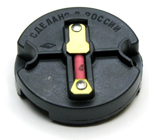
Runner
A slider is installed at the top of the rotor. It is made of plastic and has two contacts connected through a resistor. Their task is to take the voltage from the coil through the central electrode and transfer it to the side contacts of the distributor cap. The resistor is used to eliminate radio interference.
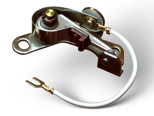
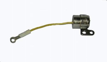
Breaker and Capacitor
The breaker mechanism includes a group of contacts and a cam with four lugs. The contacts are fixed on a movable plate, the rotation of which is provided by a ball bearing. To be able to adjust the gap between the contacts, one of the mounting holes is made in the form of an oval. The moving contact is located on a spring-loaded lever. The other contact is stationary. When at rest, they are closed.
The cam is the thickened part of the shaft. Its protrusions serve to actuate the movable contact. When the breaker-distributor shaft begins to rotate, the cam rests against the block of the movable contact with one of its protrusions, taking it to the side. Further, the protrusion bypasses the block and the contact returns to its place. This is how the low voltage circuit in the contact ignition system closes and opens in such a simple way.
Despite the fact that the voltage on the contacts is small, when they open, a spark is still formed. In order to eliminate this phenomenon, a capacitor is installed in the breaker circuit. It is screwed to the distributor body.
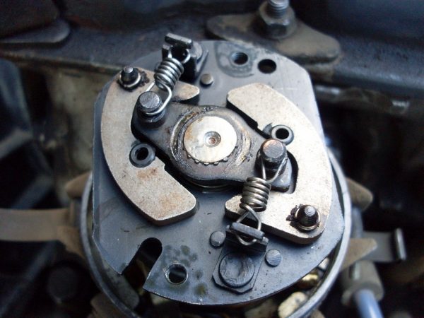
Centrifugal regulator
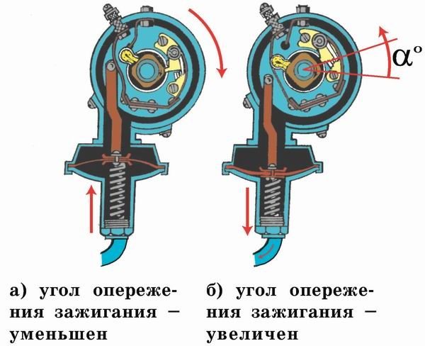
The primary adjustment of the moment of sparking in VAZ 2107 cars is carried out by turning the entire distributor. Further settings are made automatically. The function of the centrifugal regulator is to change the ignition timing depending on the number of revolutions of the engine crankshaft.
The basis of the design of the mechanism is the base and leading plates. The first is soldered to the sleeve, movably fixed on the distributor shaft. It can rotate relative to the shaft with an amplitude of 15°. From above it has two axles on which weights are installed. The drive plate is put on the upper end of the shaft. The plates are interconnected by two springs of different stiffness.
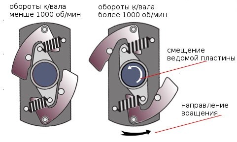
As the engine speed increases, the centrifugal force also increases. It first overcomes the resistance of a softer spring, then a stiffer one. The weights rotate on their axes and rest against the base plate with their side protrusions, forcing it to rotate together with the slider to the right, thus increasing the ignition timing.
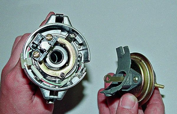
Vacuum regulator
The vacuum regulator is attached to the distributor body. Its role is to adjust the ignition angle depending on the load on the power plant. The design of the device consists of a tank, a membrane with a rod located in it, as well as a hose through which the regulator is connected to the primary chamber of the carburetor.
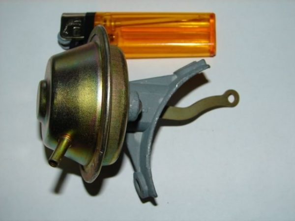
When a vacuum appears in the carburetor, it is transferred through the hose to the reservoir of our device. A vacuum is created there. When this happens, the diaphragm moves the rod, and it acts on the rotating breaker plate, turning it counterclockwise, increasing the ignition timing.
Contact-type distributor malfunctions and their symptoms
Taking into account the fact that the distributor is a rather complex device, it is subject to the influence of a number of negative factors that can disable its structural elements. That is why there can be a lot of malfunctions in the distributor. Well, as for the common breakdowns of the device, then they include:
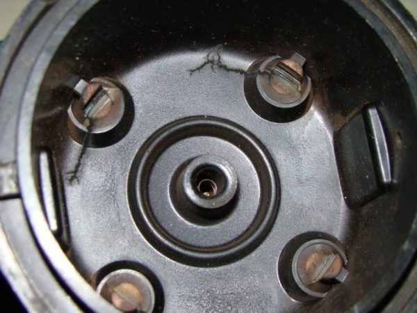
- electrical breakdown of the cover;
- wear of the central electrode or side contacts of the cover;
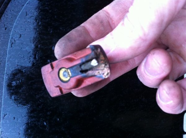
- burning of the contacts of the slider;
- electrical breakdown of the capacitor;
- violation of the gap between the contacts of the breaker;
- sliding plate bearing wear.In case of severe wear of the contacts, the cover must be replaced.
Each of the listed faults has its own symptoms, but in most cases they are of the same nature. In the event of a breakdown of the distributor cover, wear or burning of its contacts or contacts of the slider, engine performance will deteriorate. The same will happen if the gap between the contacts of the breaker is violated, they are dirty or burned. In this case, most often observed:
- vibration;
- overheat;
- misfiring;
- exhaust color change
- rare "lumbago" in the gas exhaust system;
- increase in gasoline consumption.A defective slider can be replaced by yourself
The failure of the sliding plate bearing may be accompanied by a characteristic whistle or squeal coming from under the cover.
Contactless distributor repair
To determine and eliminate the malfunction, careful diagnostics is required, which involves dismantling and disassembling the device. The only element of the distributor that can be checked without disassembling it is the capacitor. Let's start with him.
Condenser test
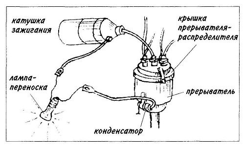
As already mentioned, the capacitor serves as a kind of spark arrester. It prevents the formation of an electric arc between the contacts of the breaker at the moment they open. To check its performance, you must perform the following steps:
- Disconnect the low voltage wire connecting the coil and distributor.
- Disconnect the capacitor wire from the distributor.
- Connect these two wires to a regular twelve-volt car lamp.
- Turn on the ignition. If the lamp lights up, the capacitor is broken.
- Replace the capacitor, check how the engine works.A burning lamp indicates a malfunction of the capacitor
Removing the distributor from the engine
The distributor is installed in the engine block on the left side. It is fixed on a special bracket with a single nut. To dismantle the device, you must:
- Disconnect the "-" wire from the battery terminal.
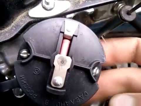
- Unfasten the two latches securing the breaker-distributor cover to the housing.
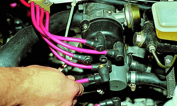
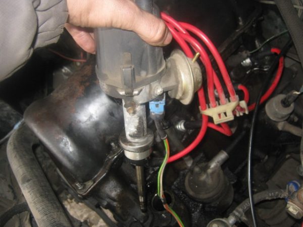
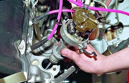
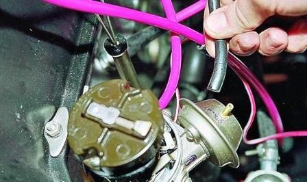
- Disconnect all armor wires from the cover.High voltage wires are disconnected from the cover of the distributor
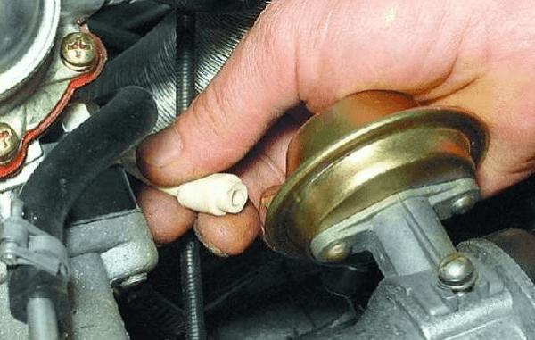
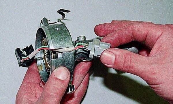
- Remove the vacuum regulator hose from the fitting on the tank.Hose can be easily removed by hand
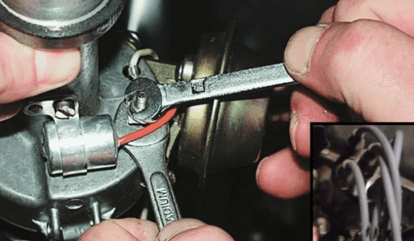
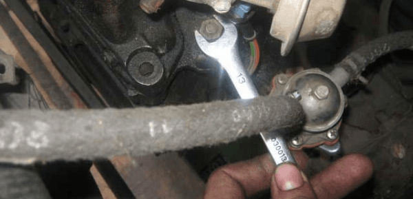
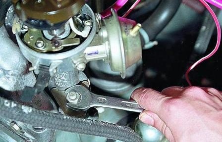
- Using a wrench to "7", unscrew the nut securing the low-voltage wire.The wire is fixed with a nut
- With the key to "13", unscrew the distributor fastening nut.The nut is unscrewed with a key to "13"
- Remove the distributor from its seat.To remove the distributor from the hole in the engine block, gently pull it up
Disassembly of the distributor and replacement of defective elements
You can determine the performance of each part of the device already at the stage of its disassembly. For this you need:
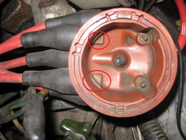
- Carefully inspect the cover of the distributor from the outside and inside. Particular attention should be paid to the central electrode (coal) and side contacts. If they are worn, damaged or severely burned, the cover must be replaced.If the contacts are broken, the cover must be replaced.
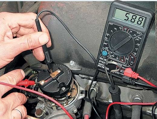
- Using an ohmmeter (multimeter turned on in ohmmeter mode), measure the resistance of the slider resistor. To do this, connect the probes of the device to the terminals of the slider. The resistance of a good resistor varies between 4-6 kOhm. If the instrument readings differ from those specified, replace the resistor or slider assembly.Resistance should be within 4-6 kOhm
- Use a thin flathead screwdriver to unscrew the two screws securing the slider. Remove the slider.The slider is attached with two screws
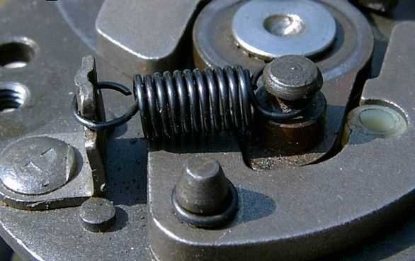
- Press the weights in opposite directions, checking the amplitude of their movement and the condition of the springs. If necessary, lubricate the weights and their axles with an anti-corrosion agent (WD-40 or similar). If you feel that the springs are stretched, replace them.If the springs are stretched and loose, they need to be replaced.
- Clean the lower part of the housing and the distributor shaft from dirt, traces of oil.
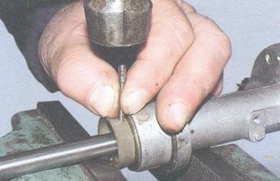
- Using a hammer and drift, knock out the shaft coupling fixing pin. Remove the pin using pliers.Using a hammer and drift, knock out the locking pin and remove it
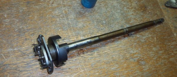
- Remove the coupling, remove the shaft from the distributor housing. Carefully inspect the shaft for wear on the splines in the lower part, as well as traces of its deformation. If such defects are found, replace the shaft.If signs of deformation are found, the shaft must be replaced.
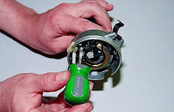
- Using the key on "7", unscrew the nut that secures the tip of the wire coming from the capacitor. Disconnect the tip, take it to the side.
- Loosen the capacitor fixing screw with a flat screwdriver. Remove condenser.The capacitor is attached to the case with a single screw.
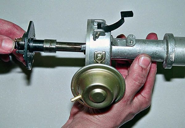
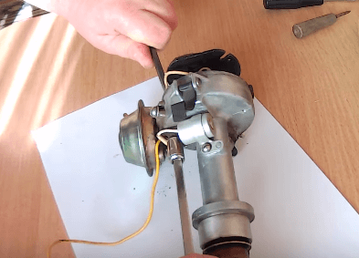
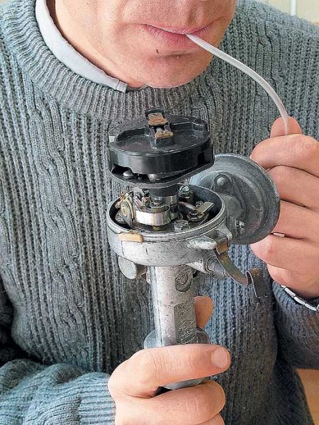
- Check the operation of the vacuum regulator. To do this, put the previously removed hose on its fitting. Use your mouth to create a vacuum at the other end of the hose. Observe the behavior of the movable breaker plate. If it responds by turning counterclockwise, the regulator is working. If not, replace the regulator.To test the regulator, it is necessary to create a vacuum
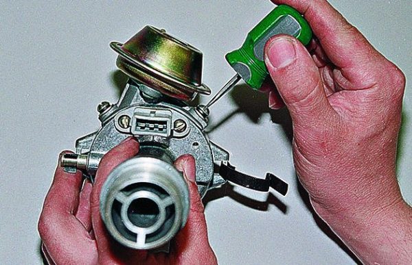
- Using a flathead screwdriver, gently slide the washer off the vacuum regulator linkage.The rod is attached with a lock washer
- Unscrew the two screws securing the regulator to the distributor housing.The regulator is fixed with two screws
- Remove the vacuum regulator.The regulator is removed together with the rod
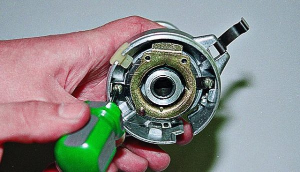
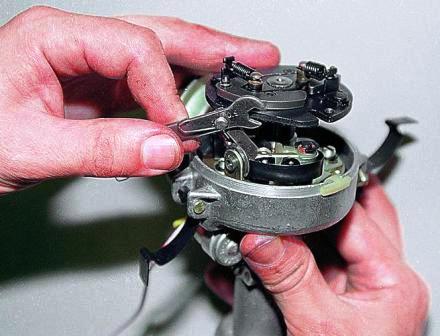
- Using the key to "7" and a slotted screwdriver, unscrew the two nuts securing the contact group (you need to hold the screw on the other side with a screwdriver).When unscrewing the screws, it is necessary to hold the nuts on the reverse side
- Remove the screw with a sleeve from the housing, remove the tip of the contact group from it.
- Disconnect contact group.The contact group is fixed with two screws
- Inspect the contacts for burning or deformation. If significant defects are found, replace the unit. If the contacts are a little burnt, clean them with fine sandpaper.
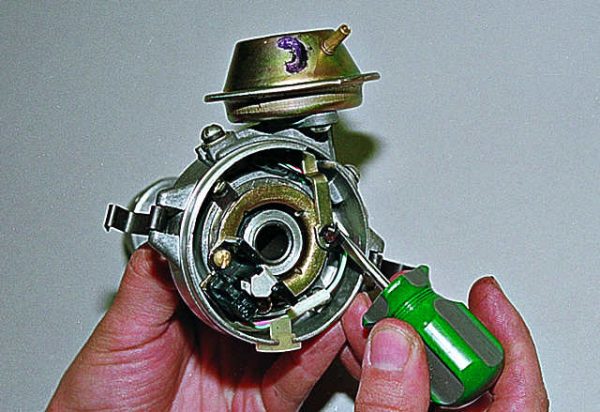
- Using a screwdriver, unscrew the fixing screws of the retaining plates.Plate screws are unscrewed with a flat screwdriver
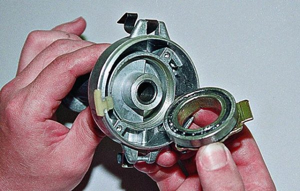
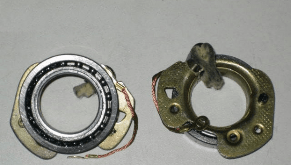
- Remove the movable plate and its bearing from the distributor housing.The movable plate is removed together with the bearing
- Check the condition of the bearing by turning it with your fingers. It should rotate easily without binding. Otherwise, the part must be replaced.The bearing should rotate easily, without binding.
Video: disassembly and repair of a contact distributor

Mounting the distributor and setting the ignition timing
The distributor is assembled after replacing defective parts in reverse order. It is not necessary to install the cover to the device at this stage. To install the distributor and set the correct ignition timing, you should:
- Shift into neutral.
- Install the distributor in its seat, not forgetting the sealing ring.The connection between the block and the distributor housing must be sealed with a special ring
- Fix the device with a nut, without tightening it until it stops.During installation, the nut does not need to be tightened.
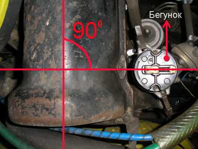
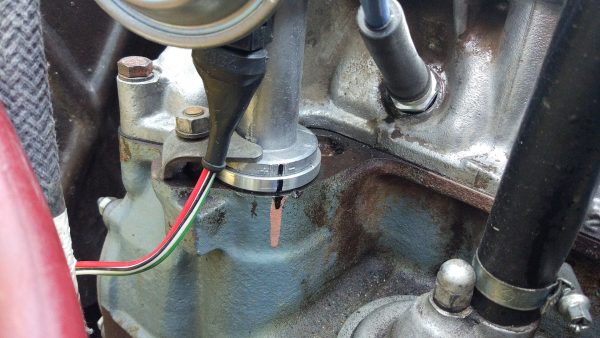
- Throw a wrench on "38" on the nut securing the crankshaft pulley. Using it, turn the crankshaft clockwise until the mark on the pulley matches the center mark on the timing cover. The distributor slider should point to the first cylinder.The slider should form a right angle with the head of the block
- Connect the wires (except high-voltage) and the hose of the vacuum regulator to the distributor.To make it easier to put the hose on the fitting, its end can be slightly lubricated with oil.
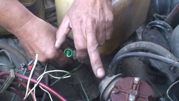
- Take a control lamp. Connect one wire from it to the contact bolt of the distributor, the second - to the "mass" of the car.The lamp is connected to the "mass" of the car and the contact bolt of the distributor
- Turn on the ignition. If the lamp lights up, grab the distributor housing with your hands and slowly turn it counterclockwise, stopping at the moment the lamp turns off. If the lamp does not light up, you need to turn the device clockwise until it turns on.The distributor must be rotated slowly until the lamp turns on
- Fix the distributor with a nut. Tighten it with a wrench to "13".
Video: setting the ignition timing

Setting the angle of the closed state of the contacts
The stability of the engine operation depends on how correctly the angle of the closed state of the contacts (the gap between the contacts) is inserted. To configure it you need:
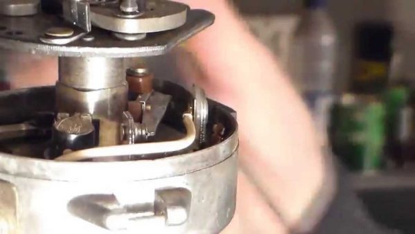
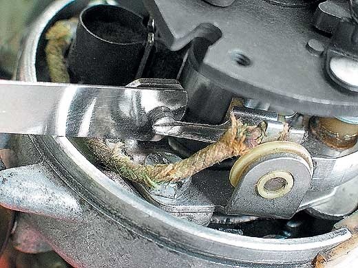
- With the key on “38”, thrown over the nut of the crankshaft pulley, turn the shaft until the moving contact lever rests on one of the cam protrusions.When the cam rests with one of its protrusions against the stop of the lever, the contacts will open
- Using a set of spark plug probes, measure the gap between the contacts. It should be in the range of 0,3–0,45 mm.The gap should be within 0,3–0,45 mm
- If the gap does not correspond to the specified distance, loosen the screw securing the contact group with a flat screwdriver. Loosen the gap adjustment screw with the same tool. To set the correct gap, it is necessary to loosen the fastening of the contact group and move it in the right direction.The gap is set by shifting the contact group
- Tighten the adjustment screw with a screwdriver.
- Re-measure the gap between the contacts.
- Repeat the adjustment if necessary.
After carrying out these works, you can install the cover on the distributor housing, connect high-voltage wires and try to start the engine.
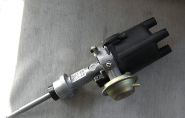
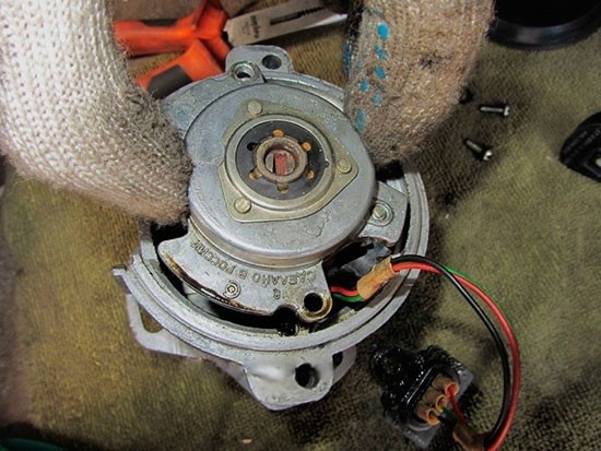
Contactless distributor
In the "sevens" with a contactless ignition system, a distributor type 38.3706 is used. As already mentioned, the design of a contactless distributor is similar to a contact one, with the exception of the mechanism responsible for creating electrical impulses in the low-voltage circuit of the system. Here, instead of the contact group, this function is performed by the Hall sensor. As for the malfunctions of the non-contact distributor, they are the same as those of the contact one, therefore, it is not advisable to consider them again. But it is worth talking about the sensor in detail.
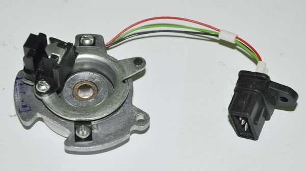
Hall Sensor
The operation of the sensor is based on the phenomenon of induction. The design of the device is based on a permanent magnet and a hollow cylindrical screen with four cutouts in the form of a crown. The screen is fixedly fixed on the distributor shaft. During the rotation of the shaft, the protrusions and cutouts of the "crown" pass through the groove of the magnet. This alternation causes a change in the magnetic field. The signals from the sensor are sent to the switch, which converts them into electrical impulses.
If the Hall sensor fails, the engine may not start at all, or it starts with difficulty and runs intermittently. The sensor cannot be repaired, but you can check it for operability yourself.
Hall sensor test
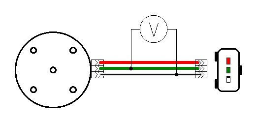
There are several ways to diagnose a sensor. The simplest of them involves replacing the device under test with a known good one. The second method is to measure the voltage at the sensor terminals with a voltmeter. Measurements are made on the 2nd and 3rd terminals of the device. The voltage between them should be 0,4-11 V. If there is no voltage or it does not meet the specified parameters, the sensor must be replaced.
You can check the device for operability by simulating its operation. To do this, disconnect the central high-voltage wire from the cover of the distributor, insert a working spark plug into it and put it so that the "skirt" touches the "ground" of the car. Next, you need to disconnect the sensor connector from the distributor, turn on the ignition and close pins 2 and 3 to each other. If a spark appears on the candle during a short circuit, the sensor is working, otherwise the device must be replaced.
Hall sensor replacement
To replace the sensor, you will need to remove the distributor from the engine. The order of further work is as follows:
- Remove the cover by unfastening the latches.
- We dismantle the runner.
- With a punch and pliers, we remove the pin of the shaft coupling.
- Remove the shaft from the housing.
- Disconnect the vacuum corrector rod.
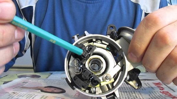
- We unscrew the two screws that secure the sensor with a flat screwdriver.The sensor is screwed on with two screws.
- Remove the Hall sensor.When the screws are removed, the sensor can be easily removed.
- We install a new part in its place.
- We assemble and install the distributor in the reverse order.
Octane corrector
It is no secret that the gasoline that we buy at gas stations often does not meet the standards provided by the car manufacturer for the normal operation of the engine. As a result of the use of such fuel, clogging of the fuel system, an increase in the amount of deposits on the parts of the piston group, and a decrease in engine performance can occur. But the most dangerous thing for the power unit is detonation, which occurs due to the use of low-octane gasoline.
In vehicles with an electronic control system, detonation is eliminated using a special sensor and control unit. Such elements are in the injector "sevens". The computer receives a signal from the sensor, processes it and automatically adjusts the ignition timing, increasing or decreasing it. There is no such equipment in carburetor VAZ 2107. Drivers have to do this manually by turning the distributor in the manner described above.
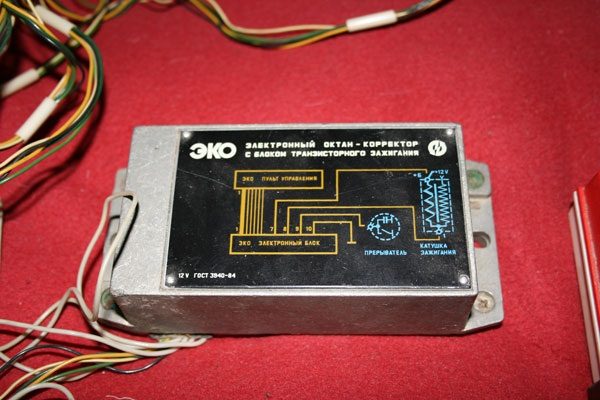
But there is a special electronic device that allows you not to adjust the ignition angle after each refueling. It's called an octane corrector. The device consists of two parts: an electronic unit that is installed in the engine compartment, and a control panel located in the passenger compartment.
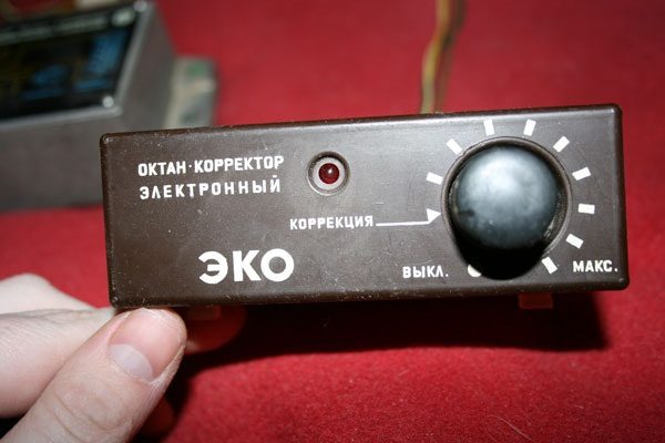
Noticing that the piston fingers begin to “ring”, the driver turns the knob on the control panel of the device, making the ignition later or earlier. Such a device costs about 200-400 rubles.
The "seven" distributor is indeed a complex device, but if you understand the design and principle of operation, you can easily maintain, repair and adjust it yourself.

