P048E High circuit exhaust pressure control valve
Content
- P048E High circuit exhaust pressure control valve
- OBD-II DTC Datasheet
- What does this mean?
- What is the severity of this DTC?
- What are some of the symptoms of the code?
- What are some of the common causes for the code?
- What are some of the P048E troubleshooting steps?
- Related DTC discussions
- Need more help with your P048E code?
P048E High circuit exhaust pressure control valve
OBD-II DTC Datasheet
High signal level in the sensor / switch position of the exhaust pressure control valve
What does this mean?
This Generic Transmission Diagnostic Trouble Code (DTC) typically applies to all OBD-II vehicles equipped with an exhaust pressure control valve sensor or switch. This may include, but is not limited to, VW, Audi, Toyota, etc. Despite the general nature, the exact repair steps may vary depending on the make / model.
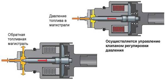
The Exhaust Pressure Control Valve (EPC) is a solenoid valve that is used to regulate back pressure at low temperatures. This helps to increase the heating of the passenger compartment, promotes cold start and windshield defrosting.
In most cases, the powertrain control module (PCM) uses information from an exhaust back pressure (EBP) sensor, an intake air temperature (IAT) sensor, and a manifold absolute pressure (MAP) sensor to determine valve control. If the PCM detects a problem with the EPC or IAT, it will disable the ECP. ECP is commonly found on diesel engines.
P048E is set when the PCM detects a high pressure control valve circuit signal. This usually indicates an open circuit.
What is the severity of this DTC?
The severity of this code is moderate to severe. It is recommended to fix this code as soon as possible.
Example of an exhaust pressure control valve: 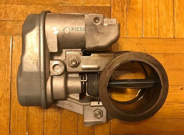
What are some of the symptoms of the code?
Symptoms of a P048E DTC may include:
- Check Engine Light
- Increased emissions
- Poor engine performance
- Hard start
What are some of the common causes for the code?
Reasons for this code may include:
- Exhaust gas pressure control valve defective
- Wiring problems
- Defective PCM
What are some of the P048E troubleshooting steps?
Begin by checking the exhaust pressure control valve and associated wiring. Look for loose connections, damaged wiring, etc. If damage is found, repair as needed, clear the code and see if it returns. Then check the technical service bulletins (TSBs) for the problem. If nothing is found, you will need to proceed to the step-by-step system diagnostics.
The following is a generalized procedure as the testing of this code differs from vehicle to vehicle. To accurately test the system, you need to refer to the manufacturer's diagnostic flowchart.
Check the wiring
Before proceeding, you need to consult the factory wiring diagrams to determine which wires are which. Autozone offers free online repair guides for many vehicles and ALLDATA offers a one-car subscription.
Check solenoid
Remove the solenoid connector. Use a digital multimeter set to ohms to check the internal resistance of the solenoid. To do this, connect a meter between the B + solenoid terminal and the solenoid ground terminal. Compare the measured resistance with the factory repair specifications. If the meter shows an out-of-specification or out-of-range (OL) reading indicating an open circuit, the solenoid should be replaced.
Check the supply side of the circuit
Make sure the car has been sitting for at least a few hours (preferably overnight) and that it is cold. Remove the solenoid connector. With the vehicle ignition on, use a digital multimeter set to DC voltage to check for power to the solenoid (usually 12 volts). To do this, connect the negative meter lead to ground and the positive meter lead to the B+ solenoid terminal on the harness side of the connector. If there is no voltage, connect a resistance meter (ignition OFF) between the B+ terminal on the solenoid connector and the solenoid supply voltage terminal on the PCM. If the meter reading is out of tolerance (OL), there is an open circuit between the PCM and the sensor that needs to be located and repaired. If the counter reads a numeric value, there is continuity.
If everything is fine up to this point, you will want to check if power is coming out of the PCM. To do this, turn on the ignition and set the meter to constant voltage. Connect the meter's positive lead to the EPC supply voltage terminal on the PCM, and the negative lead to ground. If there is no reference voltage from the PCM, the PCM is probably faulty. However, PCMs rarely fail, so it's a good idea to double check your work up to that point.
Check the grounding part of the circuit
With the vehicle ignition OFF, use a resistor DMM to test the continuity to ground. Remove the solenoid connector. Connect a meter between the solenoid ground terminal and chassis ground. If the counter reads a numeric value, there is continuity. If the meter reading is out of tolerance (OL), there is an open circuit between the PCM and the solenoid that needs to be found and repaired.
Related DTC discussions
- There are currently no related topics in our forums. Post a new topic on the forum now.
Need more help with your P048E code?
If you still need help with DTC P048E, post a question in the comments below this article.
NOTE. This information is provided for informational purposes only. It is not intended to be used as a repair recommendation and we are not responsible for any action you take on any vehicle. All information on this site is protected by copyright.