P050F Too low vacuum in the emergency braking system
Content
- P050F Too low vacuum in the emergency braking system
- OBD-II DTC Datasheet
- What does this mean?
- What is the severity of this DTC?
- What are some of the symptoms of the code?
- What are some of the common causes for the code?
- What are some steps to troubleshoot the P050F?
- Related DTC discussions
- Need more help with your P050F code?
P050F Too low vacuum in the emergency braking system
OBD-II DTC Datasheet
Too low vacuum in the emergency braking system
What does this mean?
This Generic Powertrain Diagnostic Trouble Code (DTC) is commonly applied to many OBD-II vehicles. This may include, but is not limited to, Chevrolet, Ford, VW, Buick, Cadillac, etc.
A stored code P050F means the powertrain control module (PCM) has received an input from the vacuum brake sensor (VBS) that indicates insufficient brake booster vacuum.
While there are several different types (including hydraulic and electronic) of auxiliary brake systems, this code only applies to those using engine vacuum and servo brake booster.
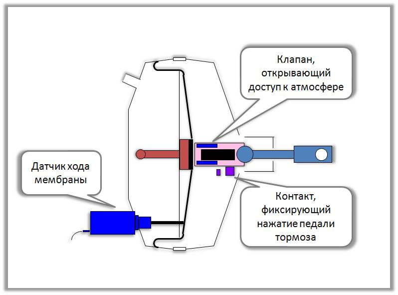
The vacuum brake booster is located between the brake pedal and the master cylinder. It is bolted to the bulkhead (usually in front of the driver's seat). It can be accessed with the hood open. One end of the booster linkage protrudes through the bulkhead and attaches to the brake pedal arm. The other end of the actuator rod pushes against the master cylinder piston, which pushes the brake fluid through the brake lines and initiates braking of each wheel.
The brake booster consists of a metal body with a pair of large vacuum diaphragms inside. This type of booster is called a double diaphragm vacuum brake booster. There are some cars that use a single diaphragm amplifier, but this is rare. When the engine is running, a constant vacuum is applied to the diaphragm, which slightly pulls the brake pedal lever. A one-way check valve (in the vacuum hose) prevents vacuum loss when the engine is under load.
While most diesel vehicles use a hydraulic booster system, others use a vacuum brake booster. Since diesel engines do not create a vacuum, a belt driven pump is used as the vacuum source. The rest of the vacuum booster system works in much the same way as the gas engine system.
A typical VBS configuration includes a pressure sensitive resistor inside a small vacuum diaphragm enclosed in a sealed plastic case. Vacuum pressure (air density) is measured in kilopascals (kPa) or inches of mercury (Hg). The VBS is inserted through a thick rubber grommet into the servo brake housing. As the vacuum pressure increases, the VBS resistance decreases. This increases the voltage of the VBS circuit. When the vacuum pressure decreases, the opposite effect occurs. The PCM receives these voltage changes as servo pressure changes and reacts accordingly.
If the PCM detects a brake booster vacuum level outside the set parameter, a P050F code will be stored and a malfunction indicator lamp (MIL) may illuminate.
Photo of the pressure (vacuum) sensor of the brake booster / VBS: 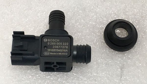
What is the severity of this DTC?
Low vacuum pressure in the brake booster can increase the amount of force required to activate the brake. This could lead to a collision with the vehicle. Problem P050F must be corrected urgently.
What are some of the symptoms of the code?
Symptoms of a P050F engine code may include:
- A hiss is heard when the brake pedal is depressed
- Increased effort required to press the brake pedal
- Other codes may be stored, including Manifold Absolute Pressure (MAP) codes.
- Problems with engine handling caused by a vacuum leak
What are some of the common causes for the code?
Reasons for this code may include:
- Internal leak in the vacuum brake booster
- Bad vacuum brake sensor
- Cracked or disconnected vacuum hose
- The non-return check valve in the vacuum supply hose is defective.
- Insufficient vacuum in the engine
What are some steps to troubleshoot the P050F?
First, if a hissing sound is heard when pressing the brake pedal and pressing the pedal requires increased effort, the brake booster is faulty and must be replaced. It is recommended to use a weighted booster (sold with a master cylinder kit) because master cylinder leakage is a major factor in booster failure.
You will need a diagnostic scanner, hand-held vacuum gauge, digital volt / ohmmeter, and a reliable source of vehicle information to diagnose the P050F code.
Diagnosis of the P050F code will begin (for me) with a visual inspection of the vacuum supply hose to the vacuum booster. If the hose is connected and in good working order, start the engine (KOER) and secure the vehicle in parking or neutral. Carefully remove the one-way check valve (at the end of the vacuum hose) from the booster and check that there is sufficient vacuum to the booster. If in doubt, you can use a hand-held pressure gauge to check the vacuum.
Engine vacuum requirements can be found in the vehicle information source. If the engine does not produce sufficient vacuum, it must be repaired before continuing with the diagnosis. If the booster has enough vacuum and appears to be in working order, consult your vehicle information source for component testing procedures and specifications. You should also find wiring diagrams, connector faceplates, and connector pinouts. These resources will be needed to make a correct diagnosis.
Step 1
Key on and engine off (KOEO), disconnect the connector from the VBS and use the positive test lead of the DVOM to check the reference voltage at the appropriate pin on the connector. Check for grounding with the negative test lead. If both reference voltage and ground are present, go to step 2.
Step 2
Use DVOM (at Ohm setting) to check VBS. Follow the manufacturer's testing procedure and specifications for testing VBS. If the sensor is out of specification, it is useless. If the sensor is good, go to step 3.
Step 3
With KOER, use the positive terminal of the DVOM nipple to measure the signal voltage at the VBS connector. Ground the negative test lead to a known good battery ground. Signal voltage should be reflected to the same extent as the MAP sensor on the scanner data display. The graph of pressure versus vacuum versus voltage can also be found on the information resource of your car. Compare the voltage found in the signal circuit with the corresponding entry on the diagram. I suspect the VBS is faulty if it doesn't match the diagram. If the voltage is within specification, go to step 4.
Step 4
Locate the PCM and use the DVOM to verify that the VBS signal circuit voltage is present there. Test the VBS signal circuit using the positive test lead from the DVOM. Connect the negative test lead to a good earth ground. If the VBS signal that you detected on the VBS connector is not present on the corresponding circuit on the PCM connector, suspect that you have an open circuit between the PCM and VBS. If all circuits are OK and VBS meets specifications; you may have a PCM problem or a PCM programming error.
- Review Technical Service Bulletins (TSB) for entries with the same code and symptoms. The correct TSB can greatly assist you in your diagnosis.
- Condemn RMB only after all other possibilities have been exhausted
Related DTC discussions
- There are currently no related topics in our forums. Post a new topic on the forum now.
Need more help with your P050F code?
If you still need help with the P050F error code, post a question in the comments below this article.
NOTE. This information is provided for informational purposes only. It is not intended to be used as a repair recommendation and we are not responsible for any action you take on any vehicle. All information on this site is protected by copyright.