P2162 Sensor Output Speed A / B Correlation
Content
- P2162 Sensor Output Speed A / B Correlation
- OBD-II DTC Datasheet
- What does this mean?
- What is the severity of this DTC?
- What are some of the symptoms of the code?
- What are some of the common causes for the code?
- What are some of the steps to troubleshoot a P2162?
- Related DTC discussions
- Need more help with the P2162 code?
P2162 Sensor Output Speed A / B Correlation
OBD-II DTC Datasheet
Output speed sensor correlation A / B
What does this mean?
This is a generic diagnostic trouble code (DTC) and is commonly applied to OBD-II vehicles. Car brands may include, but are not limited to, Ford, Chevy / Chevrolet, etc.
If your OBD-II equipped vehicle has stored the P2162 code, it means that the powertrain control module (PCM) has detected a mismatch between two separate vehicle speed sensors (output).
The individual (output) vehicle speed sensors have been labeled A and B. The sensor labeled A is usually the front-most sensor on the network, but check the specifications for the vehicle in question before making any diagnostic conclusions.
The system designed to display code P2162 uses multiple (output) vehicle speed sensors. It is likely that one is located in the differential, and the other is near the output shaft housing of the transmission (2WD) or transfer case (4WD).
The vehicle speed sensor (output) is an electromagnetic sensor that is installed in close proximity to a gear or pinion of some type of jet reactor. The rotor ring is mechanically attached to the axle, transmission / transfer case output shaft, ring gear, or drive shaft. The reactor ring rotates with the axis. When the ring teeth of the reactor pass within thousandths of an inch from the output shaft speed sensor, the magnetic field closes the input circuit of the sensor. The slots between the teeth of the reactor ring create breaks in the same circuit. These terminations / interruptions occur in rapid succession as the vehicle moves forward. These closed circuits and interrupts create waveform patterns that are accepted by the PCM (and other controllers) as vehicle speed or output shaft speed. As the speed of the waveform increases, the design speed of the vehicle and the output shaft increases. Likewise, when the input speed of the waveform slows down, the design speed of the vehicle or output shaft decreases.
The PCM continuously monitors the vehicle's (output) speed as the vehicle is moving forward. If the PCM detects a deviation between the individual vehicle speed (output) sensors that exceeds the maximum threshold (within a set period of time), code P2162 will be stored and a malfunction indicator lamp (MIL) may illuminate.
Transmission speed sensor: 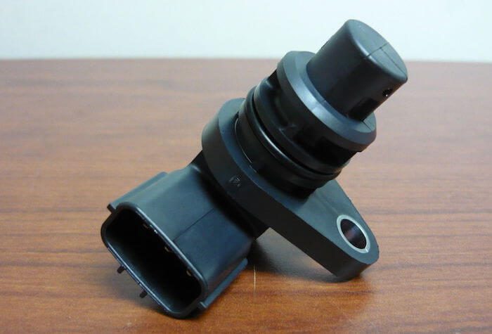
What is the severity of this DTC?
Conditions that contribute to the persistence of the P2162 code can cause incorrect speedometer calibration and erratic gearshift patterns. The code should be treated as serious and should be fixed as soon as possible.
What are some of the symptoms of the code?
Symptoms of a P2162 diagnostic code may include:
- Unstable operation of the speedometer
- Irregular gear shifting patterns
- Inadvertent activation of ABS or Traction Control System (TCS)
- ABS codes can be saved
- ABS can be disabled
What are some of the common causes for the code?
Reasons for this P2162 code may include:
- Incorrect final drive ratio (differential ring gear and gear)
- Transmission slip
- Excessive metal debris on vehicle (output) / output speed sensor magnet
- Defective vehicle speed sensor (output) / output shaft
- Cut or damaged wiring or connectors
- Broken, damaged or worn teeth of the reactor ring
- Faulty PCM or PCM programming error
What are some of the steps to troubleshoot a P2162?
A diagnostic scanner with a built-in oscilloscope will need a digital volt / ohmmeter (DVOM) and reliable vehicle information source to diagnose code P2162.
With the P2162 saved, I would make sure my automatic transmission was filled with clean fluid that did not smell burnt. If the transmission was leaking, I repaired the leak and filled it with fluid, and then operated it to make sure it was not mechanically damaged.
You will need a vehicle information resource for electrical diagrams, connector faceplates, pinouts, diagnostic flowcharts, and component test procedures / specifications. Without this information, successful diagnosis is impossible.
After visually inspecting the wiring and connectors associated with the system, I would proceed by connecting the scanner to the vehicle's diagnostic port and retrieving all stored codes and freeze frame data. I like to write this information down as it can be helpful in the diagnostic process. After that, I clear the codes and test drive the car to see if the code is cleared.
The simplest and most effective method for checking real-time vehicle speed sensor data is with an oscilloscope. If you have access to an oscilloscope:
- Connect the positive test lead of the oscilloscope to the signal circuit of the sensor under test.
- Select the appropriate voltage setting on the oscilloscope (sensor reference voltage is usually 5 volts)
- Connect the negative test lead to ground (sensor ground or battery).
- With the drive wheels off the ground and the vehicle secured, start the transmission while observing the waveform on the oscilloscope display.
- You want a flat waveform with no surges or glitches when accelerating / decelerating smoothly in all gears.
- If inconsistencies are found, suspect a faulty sensor or poor electrical connection.
Self test vehicle speed sensors (output):
- Place the DVOM on the Ohm setting and disconnect the sensor under test
- Use test leads to test the connector pins and compare your results to the sensor test specifications.
- Sensors that are out of specification should be considered defective.
Test vehicle speed sensor reference voltage (output):
- With the key on / engine off (KOEO) and the sensor under test disabled, test the reference circuit of the sensor connector with the positive test lead from the DVOM.
- At the same time, the negative test lead of the DVOM should be used to test the ground pin of the same connector.
- The reference voltage must match the specifications listed on your vehicle's information resource (typically 5 volts).
Test vehicle speed sensor signal voltage (output):
- Reconnect the sensor and test the signal circuit of the sensor under test with the positive test lead DVOM (negative test lead to sensor ground or a known good motor ground).
- With the key on and the engine running (KOER) and the drive wheels securely above the ground, start the transmission while observing the voltage display on the DVOM.
- A plot of speed versus voltage can be found in the vehicle information source. You can use it to determine if the sensor is working properly at different speeds.
- If any of the sensors you are checking do not display the correct voltage level (depending on speed), suspect that it is faulty.
If the signal circuit was showing the correct voltage level at the sensor connector, use the DVOM to test the signal circuits of the individual (output) vehicle speed sensors at the PCM connector:
- Use the positive DVOM test lead to test the appropriate signal circuit on the PCM.
- The negative test lead must be grounded again.
If there is an acceptable sensor signal on the sensor connector that is not on the PCM connector, you have an open circuit between the PCM and the sensor under test.
It is possible to suspect a PCM malfunction or a programming error only after all other possibilities have been exhausted.
- Use your vehicle information source to collect technical service bulletins (TSBs) that match the vehicle, symptoms, and stored codes in question. The code that applies to your circumstances can help you make an accurate diagnosis.
Related DTC discussions
- There are currently no related topics in our forums. Post a new topic on the forum now.
Need more help with the P2162 code?
If you still need help with DTC P2162, post a question in the comments below this article.
NOTE. This information is provided for informational purposes only. It is not intended to be used as a repair recommendation and we are not responsible for any action you take on any vehicle. All information on this site is protected by copyright.