Connecting and pinout of the towbar socket
Content
For the transportation of bulky goods, car owners often use a trailer. The trailer is connected to the machine by means of a towing hitch or a tow bar. Installing the towbar and securing the trailer is not so difficult, but you also need to take care of the electrical connections. On the trailer, direction indicators and other signals must work to warn other road users about vehicle maneuvers.
What is a towbar socket
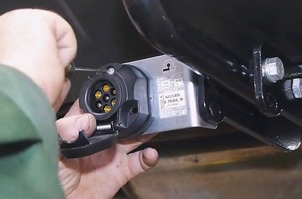
The towbar socket is a plug with electrical contacts that is used to connect the trailer to the vehicle. It is located near the towbar, and the corresponding plug is connected to it. The socket can be used to safely and correctly connect the electrical circuits of the vehicle and the trailer.
When connecting an outlet, a term such as "pinout" is used (from the English pin - leg, output). This is the pinout for correct wiring.
Connector types
There are several types of connectors depending on the type of vehicle and region:
- seven-pin (7 pin) European type;
- seven-pin (7 pin) American type;
- thirteen-pin (13 pin);
- others.
Let's analyze each type and their area of application in more detail.
XNUMX-pin European type plug
This is the most common and simpler socket type and will fit most simple trailers. It is widely used on domestic and European cars.
In the following figure, you can clearly see the appearance and pinout diagram of the seven-pin connector.
Pin and Signal Table:
| number | Code | Signal | Wire cross-section |
| 1 | L | Left Turn Signal | 1,5 mm2 |
| 2 | 54G | 12V, fog lamp | 1,5 mm2 |
| 3 | 31 | Earth (mass) | 2,5 mm2 |
| 4 | R | Right turn signal | 1,5 mm2 |
| 5 | 58R | Number illumination and right side marker | 1,5 mm2 |
| 6 | 54 | Stop lights | 1,5 mm2 |
| 7 | 58L | Left side | 1,5 mm2 |
This type of connector differs in that both the receiving and its mating parts have both types of contacts ("male" / "female"). This is done in order not to be confused by accident or in the dark. It will be almost impossible to short-circuit contacts. As you can see from the table, each wire has a cross section of 1,5 mm2except weight 2,5 mm2.
American style XNUMX-pin connector
The American type of 7-pin connector is distinguished by the presence of a reverse contact, there is also no division into right and left side lights. They are combined into one common one. In some models, brake lights and side lights are combined in one contact. Often the wires are appropriately sized and colored to facilitate the wiring process.
In the picture below, you can see the 7-pin American type circuit.
Thirteen pin connector
The 13-pin connector has respectively 13 pins. The peculiarity of this type is that there are redundant connections, several contacts for plus and minus buses and the ability to connect additional devices such as a rear view camera and others.
This scheme is most popular in the United States and some other countries where mobile homes are common. Large currents can flow through this circuit to power electrical equipment on the mobile home-trailer, the battery and other consumers.
In the figure below, you can see the diagram of a 13-pin socket.
Scheme of 13-pin towbar sockets:
| number | Color | Code | Signal |
| 1 | Yellow | L | Emergency alarm and left turn signal |
| 2 | Blue | 54G | Fog lights |
| 3 | White | 31 | Ground, minus is connected to the body |
| 4 | Green | 4 / R | Right turn signal |
| 5 | Brown | 58R | Number illumination, right side light |
| 6 | Red | 54 | Stop lights |
| 7 | Black | 58L | Left side light |
| 8 | Pink | 8 | Reverse signal |
| 9 | Orange | 9 | "Plus" wire 12V, comes from the battery to power consumers when the ignition is off |
| 10 | Gray | 10 | Provides 12V power only when the ignition is on |
| 11 | Black and White | 11 | Minus for supply pin 10 |
| 12 | Blue-white | 12 | Spare |
| 13 | Orange-white | 13 | Minus for supply pin 9 |
Connecting the towbar socket
Connecting the towbar socket is not that difficult. The socket itself is installed in the socket on the towbar, after which you need to correctly connect the contacts. To do this, you need to use the connector pinout diagram. In most cases, it is already included in the equipment kit.
For high-quality work, you will need the following tools and materials:
- purchased equipment;
- tools for dismantling and fixing parts;
- heat shrinkage, electrical tape;
- mounting plate and other fasteners;
- soldering iron;
- high-quality copper single-core wire with a cross section of at least 1,5 mm;
- connecting terminals for the contact ends of the wires;
- connection diagram.
Next, we connect the wires strictly according to the scheme. For a better connection, a soldering iron and mounting plates are used. It is important to use only a single-core wire with a cross section of 1,5 mm; a wire with a cross section of 2-2,5 mm is used for contact from the battery. You also need to take care of isolating the contacts from dust, dirt and moisture. It is obligatory to have a cover on the socket, which covers it without a trailer.
Connection Features
Cars manufactured before 2000 have analogue rear signal control circuits. It can be difficult for the driver to determine where the wires are connected, often at random. In vehicles with digital power control, this method is dangerous to electrical equipment.
Simply connecting the wires directly will not work. Most likely, the on-board computer will give an error message. In such cases, a matching unit is used in modern cars.
You can connect the towbar socket yourself, but if you are not confident in your abilities, then it will be safer to contact a specialist. Before connecting, it is imperative to check the connection points of the wires, make sure there are no fractures, rubbing elements, short circuits. The pinout diagram will help to carry out the work correctly so that all lights and signals work correctly.