Connecting LED indicators to motorcycle
Content
- Ideal for motorcycles: light emitting diodes
- Dismantling LED turn signals - let's get started
- 01 - Remove fork crown fairing
- 02 - Keshes take the hassle out of messing around
- 03 - For a good wiring harness, use an adapter cable.
- 04 - Remove the rear fairing and remove the direction indicators.
- 05 - Install a new mini-indicator with recording sleeves.
- 06 - Assembly of power resistors
- 07 - When you buy Louis resistance
- 08 - Resistors mounted under the saddle
LED technology is opening up new perspectives in vehicle design, such as motorcycle indicators. Switching to LED turn signals is not a problem even for DIY enthusiasts.
Ideal for motorcycles: light emitting diodes
State-of-the-art LED technology has opened up completely new perspectives in turn signal design: low power consumption that reduces the load on the on-board electrical system, smaller, more economical and lighter cable runs, high lighting power that allows for minimal and varied shapes and a long service life for less frequent replacement. Their small suitcase is an important advantage, especially for two-wheeled vehicles; compared to the mini LED turn signals that are currently approved for on-road use, traditional bulb turn signals seem very gross.
Unsurprisingly, many drivers switch to sleeker LED turn signals when they need to replace the original turn signals ... especially since dealer prices for genuine parts are prohibitively high.
In principle, any motorcycle with a 12V DC electrical system can be equipped with LED indicators.
Buying turn signals
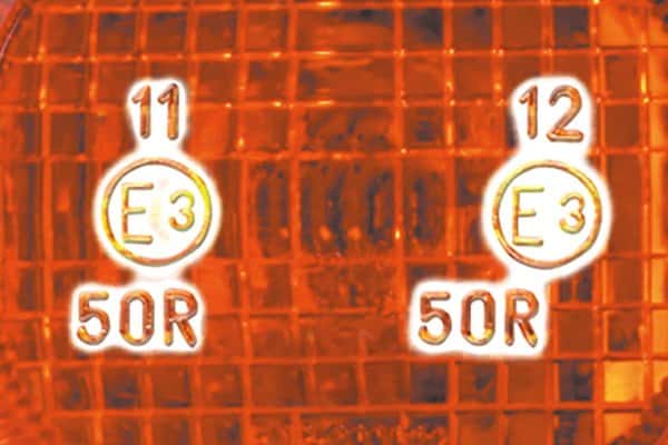
When purchasing the direction indicators, make sure that the covers have an E approval. All indicators in the Louis range have a valid E approval. Approved “front” direction indicators are identified by the identification number 1, 1a, 1b or 11, the authorized rear direction indicators are identified by the identification number 2 , 2a, 2b or 12. Many Louis line pointers are permitted as front. and behind; therefore they have two identification numbers. An indicator strip ending with an E is only permitted as front indicators and must therefore be supplemented with rear indicators. If direction indicators are available with support arms of different lengths, please note the following: according to the EU directive, direction indicators must be spaced at least 240 mm apart at the front and 180 mm apart at the rear.
Warning: to complete the assembly yourself, you will need a basic knowledge of car wiring diagrams. If you have doubts or your car is equipped with a complex electronic system, you must entrust the assembly in a specialized garage. If your vehicle is still under warranty, check with your dealer first to see if a retrofit could void your warranty.
Required technical condition
The LED power (current consumption) is significantly lower than that of traditional light bulbs. When the turn signal bulb burns out, the flashing frequency of the remaining turn signal indicator becomes too high. You have probably already encountered this situation (note: by law, the allowed blink rate is 90 cycles per minute with a plus / minus 30 tolerance). In fact, half of the "load" of the turn signal relay is now missing, which prevents it from operating at normal speed. This phenomenon is further exacerbated if, for example, you replace (on each side) respectively two standard 21W indicators with two 1,5W LED indicators. The original indicator relay then receives a load of 3 W (2 x 1,5 W) instead of 42 W (2 x 21 W), which usually does not work.
There are two solutions to this problem: either you install a dedicated LED indicator relay that is independent of the load, or you "trick" the original indicator relay by inserting electrical resistors to obtain the correct wattage.
Flasher relays or resistors?
The simplest solution here is to replace the relay, which, however, is only possible under the following conditions:
- Two separate indicators for the left / right direction indicator (no common indicator) in the passenger compartment.
- No direction indicator light and hazard warning device
- The original relay must not be integrated in the combo box (recognizable by the presence of more than three cable outlets).
If these three conditions are met, you can use our inexpensive universal LED turn signal relay. The slightly more expensive Kellermann universal turn signal relay is compatible with most hazard lights, turn signal signal devices, or only indicator lights (points 1 and 2).
If your motorcycle does not meet the requirements of points 2 and 3, we offer you specific relays from the manufacturer, which are plug and play mounted on the original socket or where you connect your car. Unfortunately, we cannot assign them depending on the model. So please have a look at our website www.louis-moto.fr under LED Relays for what relays are available and compare with the original parts. For Suzuki models we can, for example. We also offer you a combined relay box for 7 contacts.
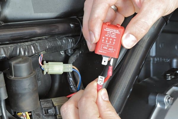
relay
Observe the polarity of the relay; incorrect connection will immediately destroy the relay electronics and void the manufacturer's warranty. Even if the wiring diagram matches the wiring diagram of the original relay, it is still possible that the polarity is different. Basically, you should first mark the polarity with the LED indicator (always follow the installation instructions for the turn signal relay).
If the male connectors don't fit, you can easily make an adapter cable so you don't have to cut the original connector out of the wire harness.
Many newer motorcycles no longer even have turn signal relays. They are already built into the central electronic unit. In this case, you can only work with resistors.
Resistors
If you cannot control your new LED turn signals with the relays mentioned, you need to use power resistors to regulate the flash rate (while keeping the original relay). Almost all LED turn signals in our range work with the original turn signal relay using a 6,8 ohm power resistor.
The note : when replacing a relay, installation of resistors is not required.
Dismantling LED turn signals - let's get started
Using the Kawasaki Z 750 as an example, we will illustrate how LED direction indicators can be mounted using resistors. The LED turn signals we use have a curved shape. That is why there are suitable models for the left front and right rear side respectively, as well as for the right front and left rear side.
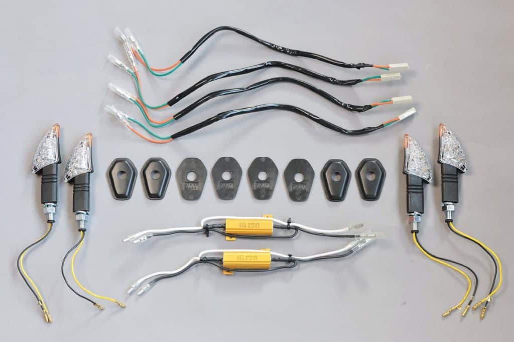
Unfortunately, the original turn signals leave large, unsightly holes when disassembled, through which new mini turn indicators can almost be threaded. Indicator covers allow you to hide them. These small covers are of course not specifically designed for the Z 750, but they are easily adaptable. If you cannot find a suitable cover for your motorcycle, you can also make suitable “flat washers” yourself out of aluminum, plastic or sheet metal.
In our example, we can use the pre-assembled adapter cables offered in the Louis range for many different models. They make it much easier to connect new indicators as they fit perfectly into the compact connectors on the vehicle side of the wiring harness. Other connectors, on the other hand, fit resistors and turn signals without any modification. If you cannot work with adapter cables, please refer to step 4.
01 - Remove fork crown fairing
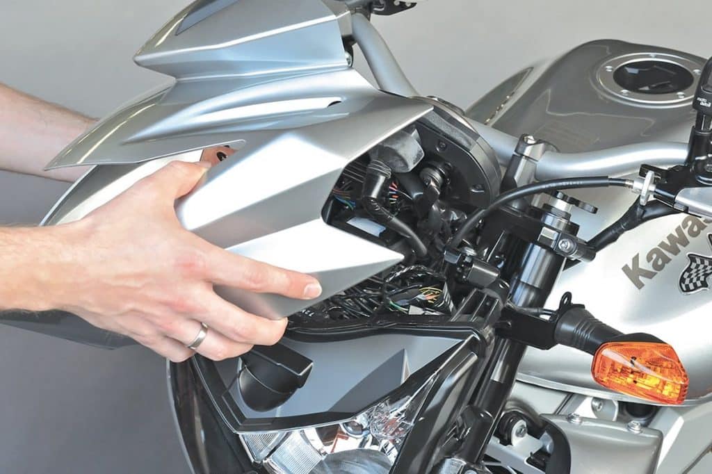
- As with any work on automotive electronics, first disconnect the negative cable from the battery to avoid short circuits.
- To replace the front turn signals, remove the front fairing and set it aside in a safe place (place a rag, blanket under it).
02 - Keshes take the hassle out of messing around
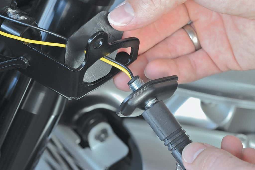
Now you can disassemble the original indicators and screw the new ones together with the covers. Remember when tightening that this is not a truck wheel bolt ...
Mini direction indicators often have a fine thread M10 x 1,25 (standard nuts are M10 x 1,5). If you lose a nut under the workbench, order a new one to replace it.
03 - For a good wiring harness, use an adapter cable.
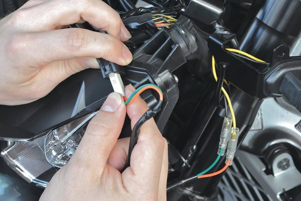
Then connect adapter cables and turn signal cables. LED direction indicators only work with correct polarity. Car manufacturers do not use cables of the same color; therefore, a wiring diagram that may be available can help you locate the positive and negative cables.
Do the same for the other side, then reassemble the fairing. Phillips will screw all screws into the plastic thread, so do not use force!
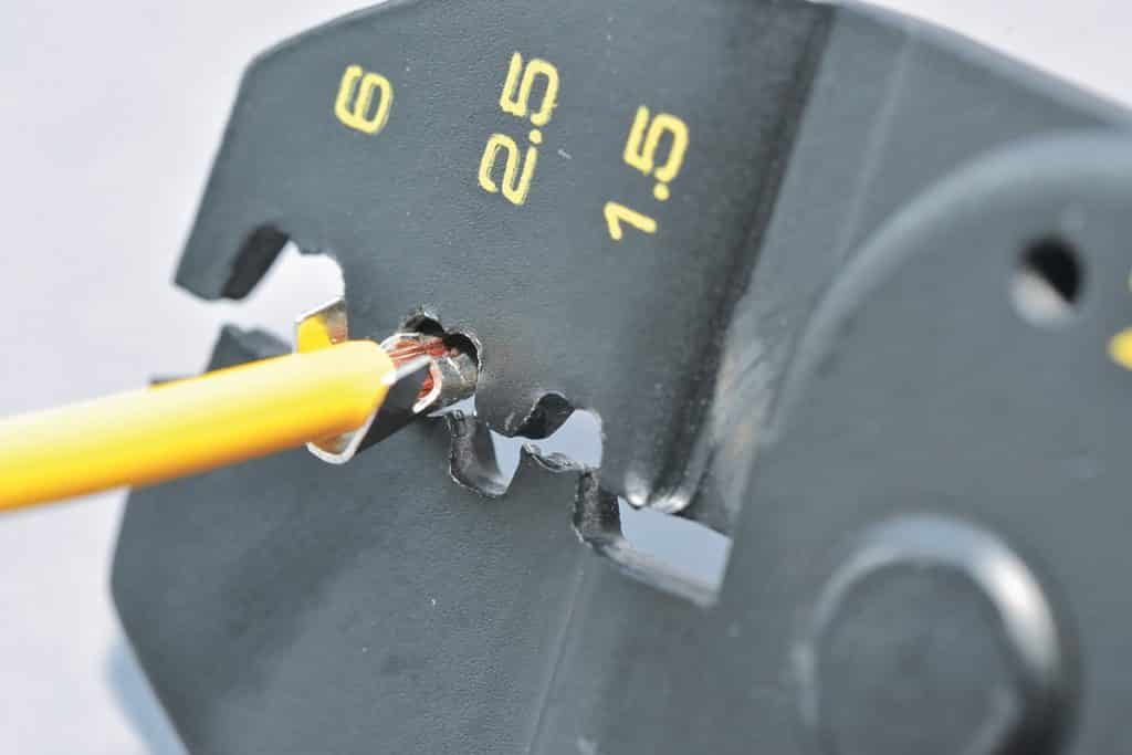
The note : If you cannot work with adapter cables, it is important to create a secure and durable cable connection. One solution is to solder the cables and then insulate them with a heat shrink jacket; the other is to crimp the cable lugs. Use Japanese round lugs which require special cable lug pliers. Both of them are also available in our professional set. There is also a clamp specially designed for insulated cable lugs, but it does NOT fit Japanese round lugs. It can be recognized by the red, blue and yellow dots on the end of the pliers. For more information on patch cables, see our tips for connecting mechanical cables.
04 - Remove the rear fairing and remove the direction indicators.
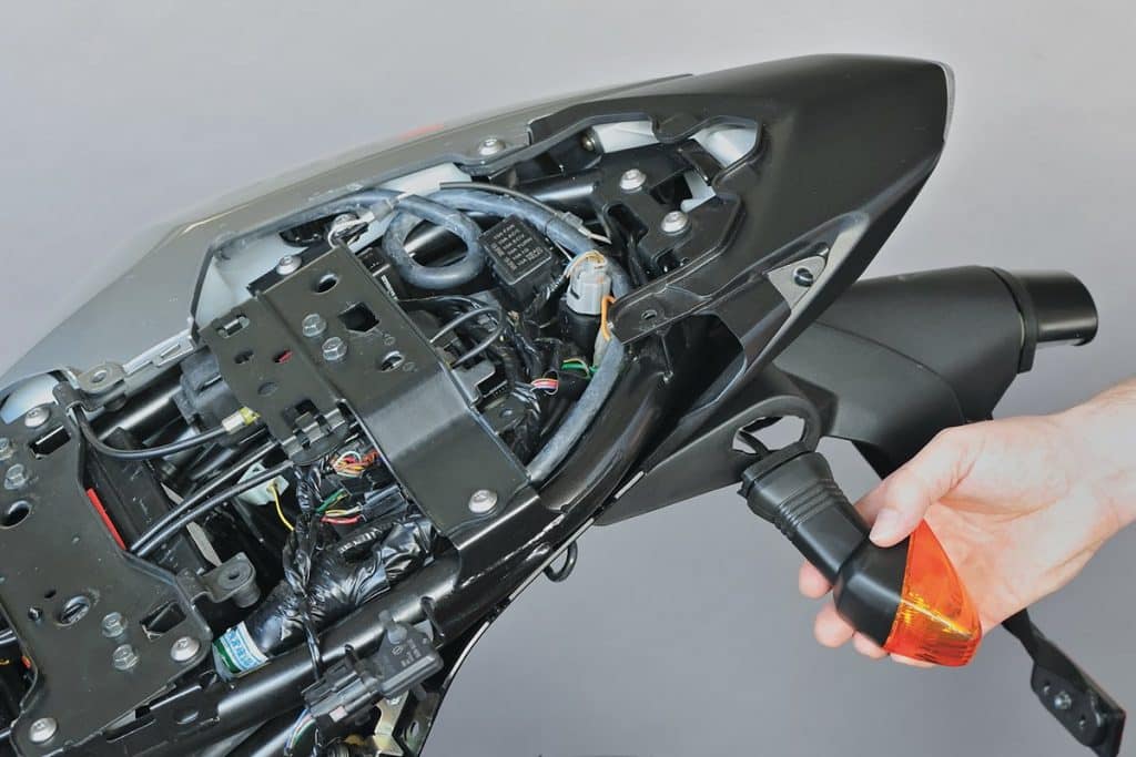
To install the rear direction indicators and power resistors, remove the seat and unscrew the rear fairing. Lay down the delicate and expensive plastic part carefully.
05 - Install a new mini-indicator with recording sleeves.
Proceed as before to remove the rear indicators and secure the new mini-indicators with the caps. The cables are routed according to the original assembly.
06 - Assembly of power resistors
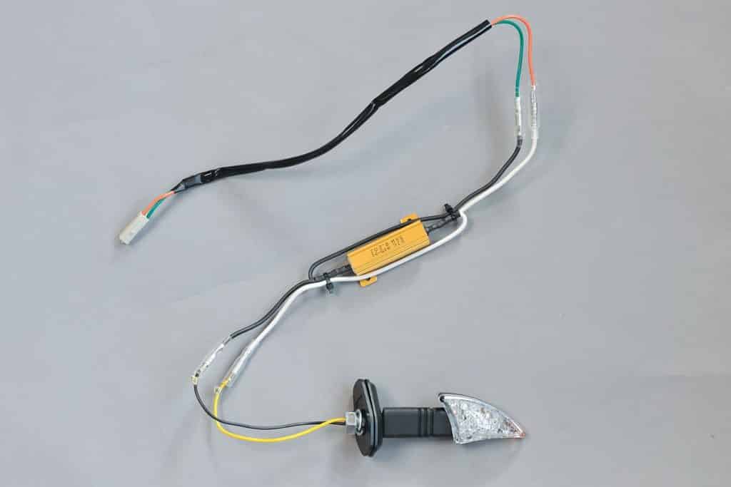
Then install resistors to the rear direction indicators. Please DO NOT install them in series but in parallel to ensure correct blinking frequency. If you buy resistors from Louis, they are already wired in parallel (see diagram below).
Resistors have no polarity, so direction doesn't matter. Louis series resistor cable lugs simplify assembly.
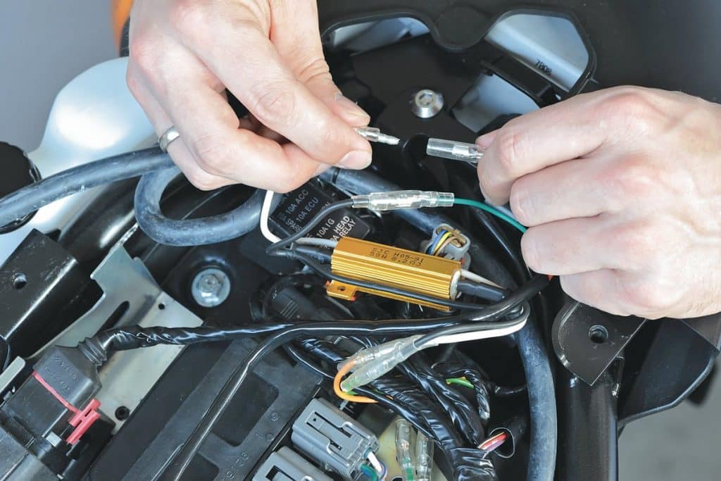
07 - When you buy Louis resistance
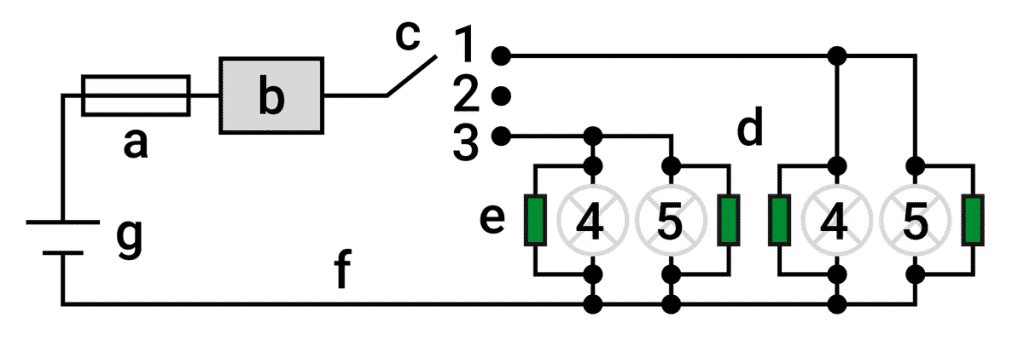
1 = Right 2 = Stop 3 = Left 4 = To 5 = Rear | a = Fuse b = Indicator relay c = Direction indicator control d = Direction indicators (bulbs) e = Resistance f = Earth cable g = Power supply / battery |
08 - Resistors mounted under the saddle
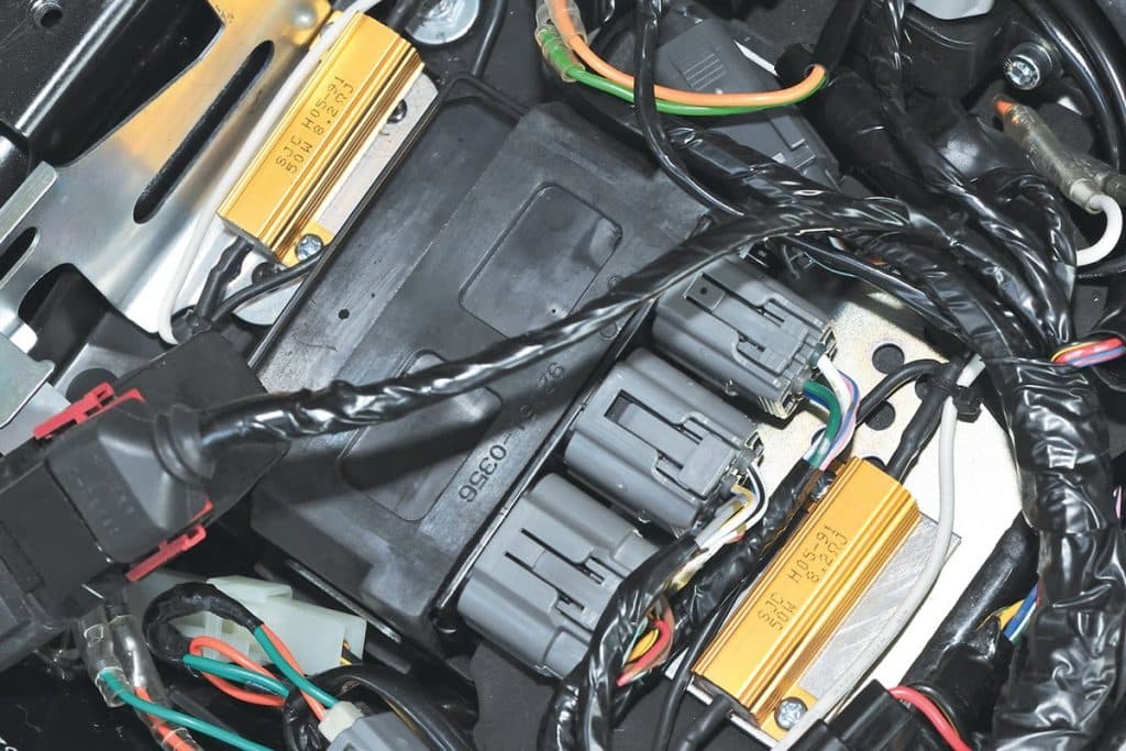
During operation, the resistors can heat up to temperatures above 100 ° C (long flashing time, alarm is triggered in case of breakdown), so air is required for cooling. Do not cover them completely and do not mount directly on a plastic stand. It may be advisable to make a small mounting plate out of sheet aluminum and place it in the vehicle.
In the case of the Z 750, the mounting location of the proposed metal plate is to the right of the control unit. We attached the right flasher circuit resistor to it with 3mm nuts and screws. We installed a resistor for the direction indicator circuit from left to right of the control unit. However, from this side it is not possible to screw the resistor directly onto the visible metal plate; In fact, another control device is installed under the plate, which could be damaged. So we screwed the resistance to the sheet and then stuffed everything under the black box.
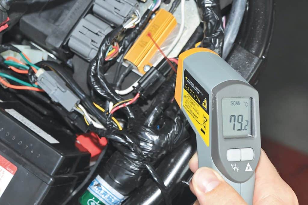
After all the components are connected and connected (don't forget the battery ground cable), you can check the direction indicators. For our part, we monitored the temperature of the resistors with an infrared thermometer. After a few minutes, their temperature already reaches 80 ° C.
Therefore, never stick resistors to the fairing with double-sided adhesive tape. Does not hold and may result in breakage! If everything works, then you can assemble the rear fairing. Conversion complete!