breakdowns of the phase sensor
Content
failure of the phase sensor, which is also called the camshaft position sensor, causes the internal combustion engine to start working in pair-parallel fuel supply mode. That is, each nozzle fires twice as often. Because of this, an increase in fuel consumption occurs, the toxicity of exhaust gases increases, and problems with self-diagnosis appear. Breakdown of the sensor does not cause more serious problems, but in case of failure, replacement is not delayed.
What is a phase sensor for?
in order to deal with possible malfunctions of the phase sensor, it is worth briefly dwelling on the question of what it is, as well as on the principle of its device.
So, the basic function of the phase sensor (or DF for short) is to determine the position of the gas distribution mechanism at a particular point in time. In turn, this is necessary in order for the ICE electronic control unit (ECU) to give a command for fuel injection at a certain point in time. namely, the phase sensor determines the position of the first cylinder. the ignition is also synchronized. The phase sensor works in tandem with the crankshaft position sensor.
Phase sensors are used on internal combustion engines with distributed phased injection. they are also used on internal combustion engines, where a variable valve timing system is used. In this case, separate sensors are often used for the camshafts that control the intake and exhaust valves.
The operation of modern phase sensors is based on the application of a physical phenomenon known as the Hall effect. It lies in the fact that in a semiconductor plate, through which an electric current flows, when it is moved in a magnetic field, a potential difference (voltage) appears. A permanent magnet is placed in the sensor housing. In practice, this is implemented in the form of a rectangular plate of semiconductor material, to the four sides of which contacts are connected - two input and two output. Voltage is applied to the first, and a signal is removed from the second. All this happens on the basis of commands coming from the electronic control unit at a particular point in time.
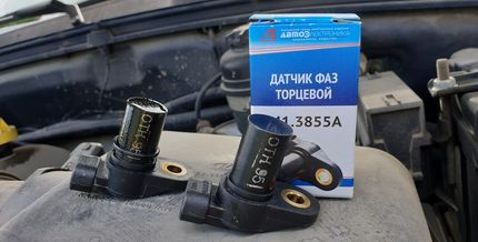
There are two types of phase sensors - slot and end. They have a different form, but work on the same principle. So, on the surface of the camshaft there is a marker (another name is the benchmark), and in the process of its rotation, the magnet included in the design of the sensor records its passage. A system (secondary converter) is built into the sensor housing, which converts the received signal into information “understandable” for the electronic control unit. End sensors have such a design when there is a permanent magnet on their end, which “sees” the passage of the benchmark near the sensor. In slot sensors, the use of the shape of the letter “P” is implied. And the corresponding benchmark on the distribution disk passes between the two planes of the case of the slotted phase position sensor.
In injection gasoline ICEs, the master disk and the phase sensor are configured so that a pulse from the sensor is formed and transmitted to the computer at the moment the first cylinder passes its top dead center. this ensures the synchronization of the fuel supply and the moment of supply of a spark to ignite the air-fuel mixture. Obviously, the phase sensor has a nominal effect on the operation of the internal combustion engine as a whole.
Signs of failure of the phase sensor
With a complete or partial failure of the phase sensor, the electronic control unit forcibly switches the internal combustion engine to the paraphase fuel injection mode. This means that the fuel injection timing is based on the readings of the crankshaft sensor. As a result, each fuel injector injects fuel twice as often. this ensures that an air-fuel mixture is formed in each cylinder. However, it is not formed at the most optimal moment, which leads to a drop in the power of the internal combustion engine, as well as excessive fuel consumption (albeit a small one, although this depends on the specific model of the internal combustion engine).
Symptoms of a phase sensor failure are:
- fuel consumption increases;
- the toxicity of exhaust gases increases, it will be felt in the smell of exhaust gases, especially if the catalyst is knocked out;
- The internal combustion engine starts to work unstably, most noticeably at low (idle) speeds;
- the dynamics of acceleration of the car decreases, as well as the power of its internal combustion engine;
- the Check Engine warning light is activated on the dashboard, and when scanning for errors, their numbers will be associated with the phase sensor, for example, error p0340;
- at the moment of starting the internal combustion engine in 3 ... 4 seconds, the starter turns the internal combustion engine “idle”, after which the engine starts (this is due to the fact that in the first seconds the electronic control unit does not receive any information from the sensor, after which it automatically switches to emergency mode, based on data from the crankshaft position sensor).
In addition to the above symptoms, often when the phase sensor fails, there are problems with the car's self-diagnosis system. namely, at the moment of starting, the driver is forced to turn the starter for a little longer than usual (usually 6 ... 10 seconds, depending on the car model and the internal combustion engine installed on it). And at this time, self-diagnosis of the electronic control unit takes place, which leads to the formation of appropriate errors and the transfer of the internal combustion engine to emergency operation.
failure of the phase sensor on a car with LPG
It is noted that when the internal combustion engine is running on gasoline or diesel fuel, the unpleasant symptoms described above are not so acute, so often many drivers use cars with a faulty phase sensor for a long time. However, if your car is equipped with fourth-generation and higher gas-balloon equipment (which uses its own “smart” electronics), then the internal combustion engine will work intermittently, and driving comfort will drop sharply.
namely, the fuel consumption will increase significantly, the air-fuel mixture can be lean or, conversely, enriched, the power and dynamics of the internal combustion engine will significantly decrease. All this is due to the inconsistency in the operation of the software of the electronic control unit of the internal combustion engine and the HBO control unit. Accordingly, when using gas-balloon equipment, the phase sensor must be changed immediately after its failure is detected. Using a car with a disabled camshaft position sensor is harmful in this case not only for the internal combustion engine, but also for gas equipment and its control system.
Causes of breakage
The basic cause of failure of the phase sensor is its natural wear and tear, which occurs over time for any part. namely, due to the high temperature from the internal combustion engine and constant vibration in the sensor housing, its contacts are damaged, the permanent magnet can be demagnetized, and the housing itself is damaged.
Another main cause is sensor wiring problems. namely, the supply/signal wires may be broken, due to which the phase sensor is not supplied with supply voltage, or the signal does not come from it via the signal wire. it is also possible to break the mechanical fastening on the "chip" (the so-called "ear"). Less often, a fuse can fail, which is responsible, among other things, for powering the phase sensor (for each specific car, it will depend on the complete electrical circuit of the car).
How to check the phase sensor

Checking the performance of the internal combustion engine phase sensor is carried out using a diagnostic tool, as well as using an electronic multimeter capable of operating in DC voltage measurement mode. We will discuss an example of verification for the phase sensors of a VAZ-2114 car. Model 16 is installed on models with 21120370604000-valve ICE, and model 8-21110 is installed on 3706040-valve ICE.
First of all, before diagnostics, the sensors must be dismantled from their seat. After that, you need to make a visual inspection of the DF housing, as well as its contacts and terminal block. If there is dirt and / or debris on the contacts, you need to get rid of it with alcohol or gasoline.
To check the sensor of the 8-valve motor 21110-3706040, it must be connected to the battery and an electronic multimeter according to the diagram shown in the figure.
then the verification algorithm will be as follows:
- Set the supply voltage to +13,5 ± 0,5 Volts (you can use a conventional car battery for power).
- In this case, the voltage between the signal wire and the "ground" must be at least 90% of the supply voltage (that is, 0,9V). If it is lower, and even more so equal to or close to zero, then the sensor is faulty.
- Bring a steel plate to the end of the sensor (with which it is directed to the camshaft reference point).
- If the sensor is working, then the voltage between the signal wire and the "ground" should be no more than 0,4 volts. If more, then the sensor is faulty.
- Remove the steel plate from the end of the sensor, the voltage on the signal wire should again return to the original 90% of the supply voltage.
To check the phase sensor of a 16-valve internal combustion engine 21120370604000, it must be connected to the power supply and a multimeter according to the diagram shown in the second figure.
To test the appropriate phase sensor, you will need a metal piece measuring at least 20 mm wide, at least 80 mm long and 0,5 mm thick. The verification algorithm will be similar, however, with other voltage values:
- Set the supply voltage on the sensor equal to +13,5±0,5 Volts.
- In this case, if the sensor is working, then the voltage between the signal wire and the "ground" should not exceed 0,4 volts.
- Place a pre-prepared steel part in the sensor slot where the camshaft reference is placed.
- If the sensor is OK, then the voltage on the signal wire must be at least 90% of the supply voltage.
- Remove the plate from the sensor, while the voltage should again drop to a value of no more than 0,4 volts.
In principle, such checks can be performed without dismantling the sensor from its seat. However, in order to inspect it, it is better to remove it. Often, when checking the sensor, it is worth checking the integrity of the wires, as well as the quality of the contacts. For example, there are times when the chip does not hold the contact tightly, which is why the signal from the sensor does not go to the electronic control unit. also, if possible, it is desirable to “ring out” the wires going from the sensor to the computer and to the relay (power wire).
In addition to checking with a multimeter, you need to check for appropriate sensor errors using a diagnostic tool. If such errors are detected for the first time, then you can try to reset them using software tools, or simply by disconnecting the negative battery terminal for a few seconds. If the error reappears, additional diagnostics is needed according to the above algorithms.
Typical phase sensor errors:
- P0340 - no camshaft position determiner signal;
- P0341 - the valve timing does not match the compression / intake strokes of the cylinder-piston group;
- P0342 - in the electrical circuit of the DPRV, the signal level is too low (fixed when shorted to ground);
- P0343 - the signal level from the meter exceeds the norm (usually appears when the wiring is broken);
- P0339 - An intermittent signal is coming from the sensor.
so, when these errors are detected, it is desirable to carry out additional diagnostics as soon as possible so that the internal combustion engine operates in the optimal operating mode.