Where is the fuse for the alternator
Content
The circuits of automotive electrical equipment are protected by fusible links that prevent overheating and ignition of the wiring. Knowledge of the Priora fuse circuit will allow the owner to detect a faulty element. Also, a burnt element can be used to install an offline generating set.
Relay and fuse blocks on the LADA Priora car
The VAZ Priora passenger car, regardless of the type of engine installed, is equipped with various junction boxes. They are located under the hood and inside the car. The use of several boxes made it possible to separate circuits with large and small currents. In addition, small-sized separate mounting blocks are installed, introduced as the configuration expands.
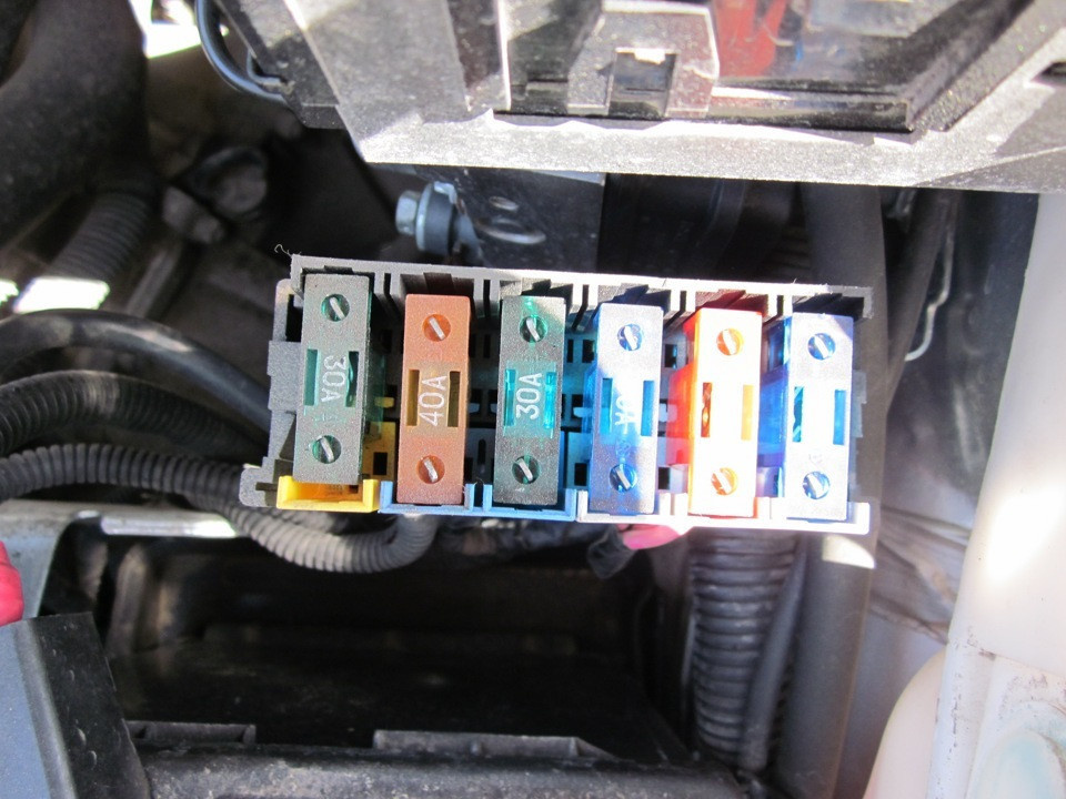
Main power fuse box
The power circuits of the car are protected by inserts installed on the positive terminal of the battery. The unit is designed to protect circuits with maximum currents. To access the fuses, you need to remove the plastic cover, this can be done without the help of tools.
Block diagram and its location in the car
The removal of the most powerful Lada Priora circuits into a separate unit located next to the battery provided maximum protection against power surges in the car.
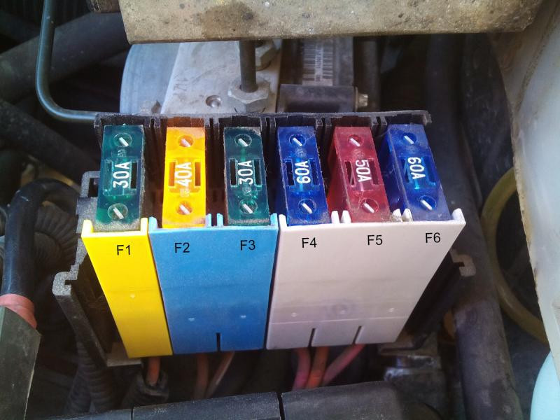
The location and designation of the inserts is indicated in the photo. Depending on the year of manufacture and the installed equipment, it is possible to install fuses of different ratings.
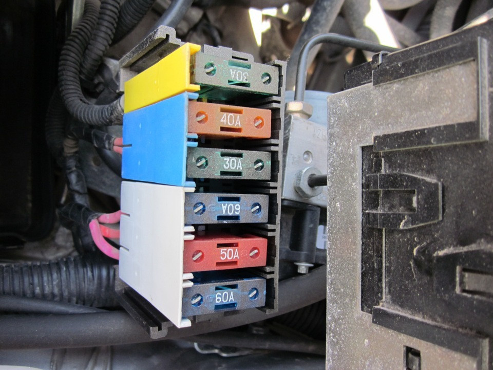
Priora stem insert block
Explanation of fuse designations
Purpose and qualification of the liners of the main unit.
| Number on the photo | Denomination, to | Element assignment |
| F1 | thirty | Protection of power circuits of the ECM system (management of the operation of the propulsion system) |
| F2 | 40 (there is an option for 60 A) | Cooling fan motor power supply, auxiliary ignition controller, glass heating filaments, drive control unit |
| F3 | 30 (there is an option for 60 A) | Controls the operation of the cooling fan motor, horn, standard alarm siren, ignition control switch, instrument panel circuits, interior lighting, brake light power and cigarette lighter |
| F4 | 60 | First generating circuit |
| F5 | fifty | Power and motor control for electromechanical power steering |
| F6 | 60 | Scheme of the second generator |
The Lada Priora fuse diagram above is relevant for cars without an anti-lock braking system. The introduction of a hydroelectronic assembly in the car of the Priora-2 series entailed a change in the purpose of the liners.
The operation of the battery fuses for Priora vehicles with ABS (starting from the one closest to the terminal):
- F1 - ECU protection (30A);
- F2 - power steering (50 A);
- F3 - generator circuits (60 A);
- F4 - similar to F3;
- F5 - power supply of the ABS unit (40 A);
- F6: Similar to F5, but rated at 30A.
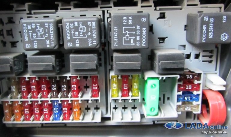
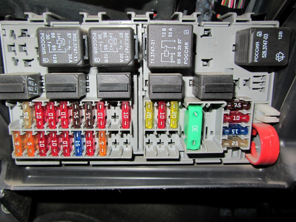
Mounting block: relays and fuses in the passenger compartment
The block includes fuses, various relays and clamps, designed to simplify the procedure for replacing burned-out inserts. The filling of the device depends on the configuration of the car.
Block diagram and its location in the car
The unit is located in the plastic frame of the dashboard at the bottom on the driver's side. The box is closed from the outside with a removable lid installed around the steering column and fixed with three locks located along the bottom edge. To remove the cover, rotate the latches 90 degrees and remove the element from the latches by pulling it towards you.

An oval marks the location of the block
In vehicles, fuse ratings may vary depending on the year of manufacture of the vehicle and equipment. To determine the value of the fusible link, use the instruction manual for Lada Priora.
When it comes to repairing fuses, keep in mind that the instructions for the Lada Priora car change several times a year. It is not recommended to use the manual of another car.
The "standard" version with the additional installation of an air conditioner has differences in the Priora fuse circuit. The elements that provide protection for the device are located in a separate engine compartment, which will be discussed below. The helmet itself has not changed.
"Normal" version of the air-conditioned unit
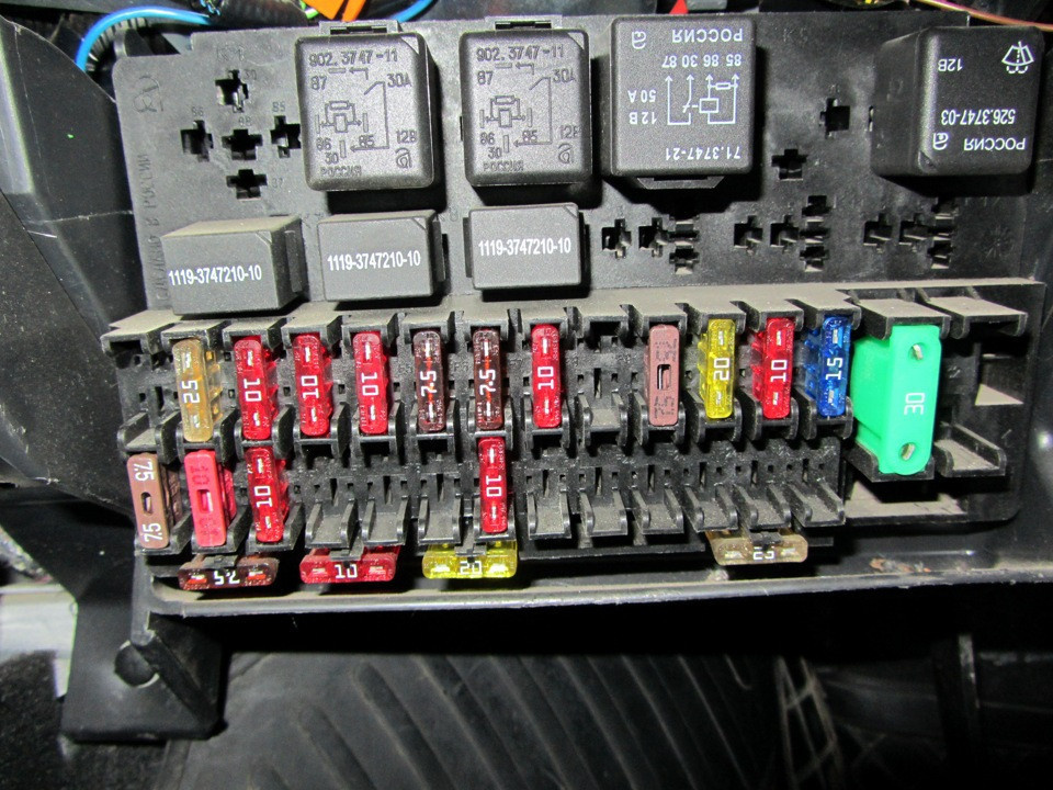
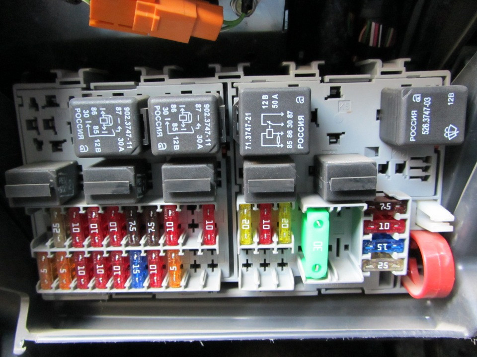
The purpose of the fusible inserts in the "lux" automatic version does not differ from the "standard + air conditioner" version. On cars, you can find both the block model 1118-3722010-00 and the Delphi variant 15493150. The boxes differ slightly in appearance, as well as in the location of interchangeable inserts and the presence of Delphi calipers.
Delphi Deluxe mounting block option
With the start of production of the modernized Priora-2, the filling of the hull has changed somewhat. In the cabin blocks of cars, only one place is empty for the relay, and two cells for fuses.
Block in Priore-2
Explanation of the designations of fuses and relays
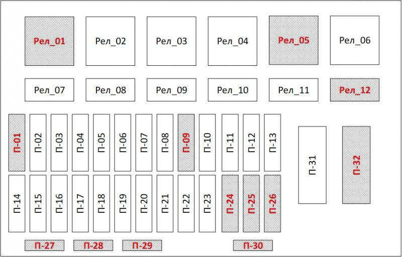
Deciphering the fuses in the "norm" option.
| Number on the scheme | Denomination, to | Goal |
| P-1 | 25 | Radiator fan power |
| P-2 | 25 | Heated rear window |
| P-3 | 10 | Headlight filaments on starboard side |
| P-4 | 10 | Same left |
| P-5 | 10 | Horn |
| P-6 | 7,5 | Left low beam |
| P-7 | 7,5 | Likewise on the starboard side |
| P-8 | 10 | alarm siren |
| P-9 | 25 | Electric engine heater |
| P-10 | 7,5 | Power supply for instrument panel (terminal 30), brake filament and interior lighting |
| P-11 | twenty | Windshield cleaning system. Rear window heating control |
| P-12 | 10 | Power connection for the second instrument panel (terminal 15) |
| P-13 | fifteen | Easier |
| P-14 | 5 | Left side markers |
| P-15 | 5 | Similarly on the right |
| P-16 | 10 | Connecting the power supply of the ABS unit (terminal 15) |
| P-17 | 10 | Left fog lamp |
| P-18 | 10 | Same for the right side |
| P-19 | fifteen | Driver and passenger seat heating filaments |
| P-20 | 5 | Conventional immobilizer system |
| P-21 | 7,5 | Rear fog light |
| P-22-30 | No one | Reservation |
| P-31 | thirty | Supply chains |
| P-32 | No one | Reservation |
Relay configuration "norm":
- 1 - cooling system fan;
- 2 — inclusion of glass heating;
- 3 - starter;
- 4 - additional ignition circuits;
- 5 - reserve;
- 6 - system for cleaning and supplying water to the windshield;
- 7 - high beam;
- 8 — horn;
- 9 - standard alarm siren;
- 10 - reserve;
- 11 - reserve;
- 12 - reserve.
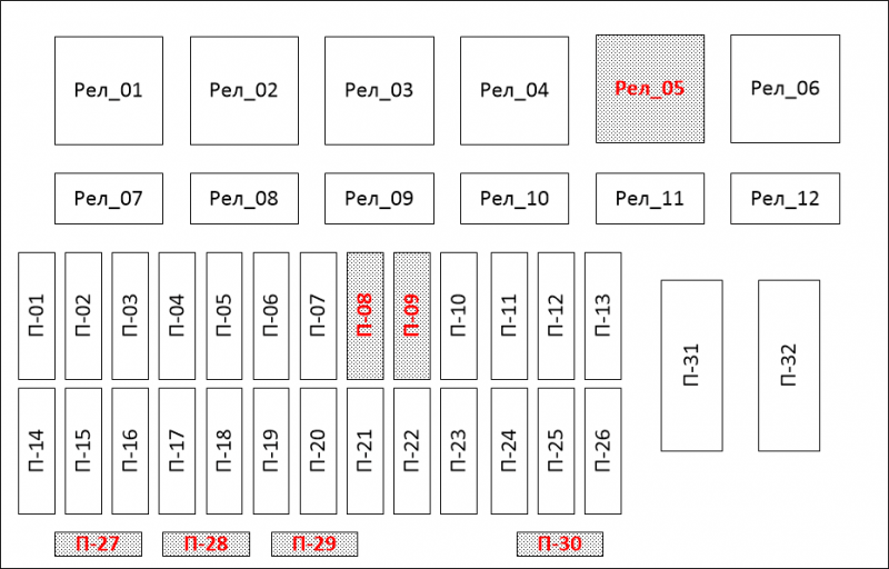
Assignment of fuses in the "standard" version with air conditioning.
| Number on the scheme | Denomination, to | Goal |
| P-1 | none | Reserve a seat |
| P-2 | 25 | Window heating controllers, electrical accessories. Glass Heating Power Schemes |
| P-3 | 10 | Starboard high beam, instrument cluster and high beam indicator |
| P-4 | 10 | Left high beam |
| P-5 | 10 | Horn control and horn power circuit |
| P-6 | 7,5 | Left low beam headlamp |
| P-7 | 7,5 | Starboard analogue |
| P-8 | 10 | Standard power and siren control |
| P-9 | No one | Reserve a seat |
| P-10 | 10 | Power supply for the instrument cluster (terminal 20), brake signal circuits (including additional), interior lighting systems |
| P-11 | twenty | Windshield wiper and washer circuits (windshield and rear), heated rear window, safety control (airbags) |
| P-12 | 10 | Terminal 21 in instrument cluster, electrical system, power steering, parking sensors (if equipped), reverse indicator |
| P-13 | fifteen | Easier |
| P-14 | 5 | Left Side Marker Circuits, License Plate Light, Part of Powertrain Control Module Circuits |
| P-15 | 5 | Starboard parking light circuits and glove box lighting system |
| P-16 | 10 | ABS block |
| P-17 | 10 | Left front fog lamp |
| P-18 | 10 | Similarly on the right |
| P-19 | fifteen | Seat heating and control buttons |
| P-20 | 10 | Start relay for headlights, heater, rain sensor and climate control (automatic) and lighting |
| P-21 | 5 | Diagnostic connector, clock and air conditioning controller |
| P-22-30 | No one | Reserve a seat |
| P-31 | thirty | Electrical accessories unit, control of the driver's door button module, illumination of the left door opening |
| P-32 | No one | Reserve a seat |
Relay in the "standard" version with air conditioning:
- 1 - spare seat;
- 2 - heated rear window with electrically heated wires;
- 3 - starter;
- 4 - additional switch;
- 5 - spare place;
- 6 - ensure the operation of the wipers at a constant high speed (in automatic mode);
- 7 - high beam;
- 8 — horn;
- 9 - standard alarm siren;
- 10 - fog lamp on the front bumper;
- 11 - front seat heating regulator;
- 12 - spare place.
The following relays can be located in the Priora units of the "lux" version:
- 1 - automatic headlight control (includes position and dipped beam);
- 2 - rear window heating wires;
- 3 - launch control;
- 4 - additional element;
- 5 - reserve;
- 6 - enable faster operation of the wiper blades (in automatic mode);
- 7 - high beam regulator;
- 8 — horn;
- 9 - standard alarm siren;
- 10 - front fog lights;
- 11 - the work of heating the driver's and passenger seats;
- 12 - wiper operation in intermittent mode or at low speed.
See also: How to make antifreeze with your own hands from alcohol
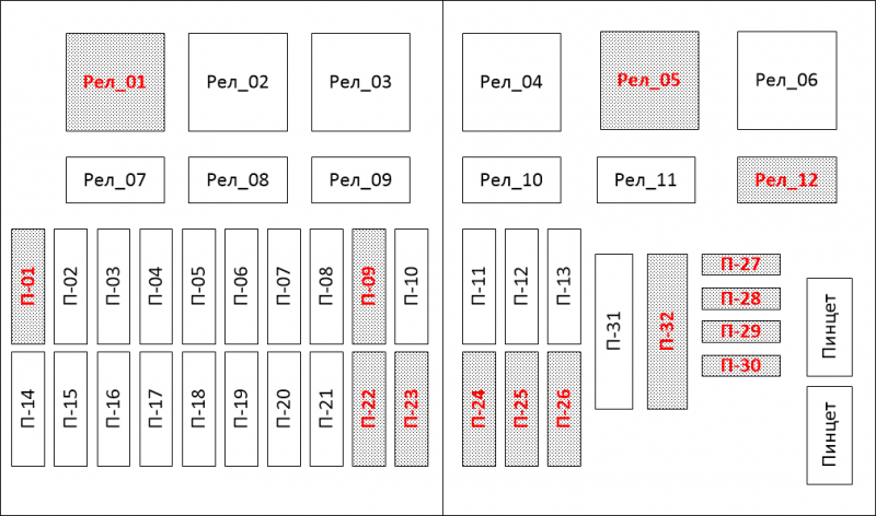
The functions of the fuses in the Priora-2 block are distributed according to the table.
| Number on the scheme | Denomination, to | Goal |
| P-1 | 25 | radiator fan motor |
| P-2 | 25 | Rear window with electric heating |
| P-3 | 10 | Ensuring the correct operation of the high beam |
| P-4 | 10 | Same for the left side |
| P-5 | 10 | Horn |
| P-6 | 7,5 | Low beam on port side |
| P-7 | 7,5 | The same on the right side |
| P-8 | No one | Reservation |
| P-9 | No one | Reservation |
| P-10 | 7,5 | Instrument cluster and electric brake lights |
| P-11 | twenty | Body electronics control unit and washer system |
| P-12 | 10 | Additional instrument panel power supply (terminal 15) |
| P-13 | fifteen | Easier |
| P-14 | 5 | Harbor alarm circuits and license plate lights |
| P-15 | 5 | Starboard dimensions, glove compartment and trunk lighting |
| P-16 | 10 | ABS valve body |
| P-17 | 10 | Left fog lamp |
| P-18 | 10 | Right fog lamp |
| P-19 | fifteen | Seat heating power and controls |
| P-20 | 10 | SAUKU (automatic operation of the air conditioner) |
| P-21 | 10 | Body electronics control unit, diagnostic connector, climate control system |
| P-22 | 5 | Control unit located in the driver's door |
| P-23 | 5 | Daytime running light system |
| P-24 | fifteen | Airbag monitoring |
| P-25 | twenty | Body electronics control unit, windshield washer fluid supply |
| P-26 | 5 | Rear fog lights |
| P-27-30 | No one | Reservation |
| P-31 | thirty | Body electronics control unit (main power supply) |
| P-32 | thirty | Heater Fan Motor Power Circuit |
The Priora-2 relay list is as follows:
- 1 - start and stop the electric motor of the fan of the cooling system;
- 2 — inclusion of heating of back glass;
- 3 - boot boot;
- 4 - switching signals from the ignition switch;
- 5 - reserve cell;
- 6 - windshield cleaning system;
- 7 - high beam power regulator;
- 8 - a similar device for dipped beam headlights;
- 9 - the work of the horn;
- 10 - fog lights;
- 11 - front row seat heating system;
- 12 - additional relay.
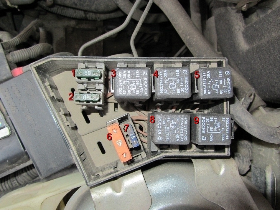
Additional mounting block
Various fuses are brought to the additional block, including the protection of the fuel pump. The device also contains a main control relay that ensures the operation of the entire electrical system of the car.
Block diagram and its location in the car
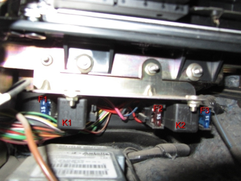
The Priora additional unit is located in the front passenger's footwell near the center console. The device is covered with a removable plastic panel, which is mounted on self-tapping screws. The installation location and overall view of the unit with the cover removed are shown below.
Explanation of the designations of fuses and relays
Assignment of inserts of the additional block on the Priore.
| Element designation | Denomination, to | Function |
| F1 | fifteen | Main controller power protection and starter interlock system |
| F2 | 7,5 | Motor driver circuit protection |
| F3 | fifteen | Fuel pump motor protection |
| K1 | Relay | Main controller |
| K2 | Relay | Fuel pump control |
Replacing the fuel pump fuse is shown in a video filmed by the V Priore channel.
Control and protection unit for climatic devices in LADA Priora cars
When installing the air conditioning system on the machine, an additional box is used in which the relays and fuses are located. There are several types of devices that differ in the arrangement of elements.
Block diagram and its location in the car
The group is installed in the engine compartment on a support welded to the glass of the left shock absorber. From above the device is closed by an easily removable plastic casing. From accidental removal of the casing is held by plastic clips.
The photo below shows a comparison of Halla and Panasonic devices. The difference between the blocks is clearly visible: the Panasonic product uses an additional relay that provides a higher rotational speed of the heater motor shaft.
Explanation of the designations of fuses and relays
The distribution of elements in the production block Halla.
| Number on the scheme | Denomination, to | Function |
| а | thirty | Right fan power protection |
| two | thirty | Similarly for the left |
| 3 | — | Right fan drive start |
| 4 | — | Additional controller for sequential connection of fan motors |
| 5 | — | Starting the left fan drive |
| 6 | 40 | Power supply for the fan located in the heating block |
| 7 | fifteen | Compressor electromagnetic clutch protection |
| 8 | — | Fan control on the heater |
| 9 | — | Compressor clutch control |
The distribution of elements in the production division of Panasonic.
| Number on the scheme | Denomination, to | Function |
| а | — | Maximize heater output (engine speed) |
| two | — | Right fan drive start |
| 3 | — | Additional controller for sequential connection of fan motors |
| 4 | — | Starting the left fan drive |
| 5 | thirty | Left fan power protection |
| 6 | thirty | Likewise for law |
| 7 | 40 | Power supply for the fan located in the heating block |
| 8 | fifteen | Compressor electromagnetic clutch protection |
| 9 | — | Fan control on the heater |
| 10 | — | Compressor clutch control |
Design description and fuse table
The on-board network is direct current, with a rated voltage of 12 V. The electrical equipment is made according to a single-wire circuit: the negative terminals of sources and consumers of electricity are connected to the "ground": the body and the power unit of the car, which act as a second cable.
When the engine is off, the switched on consumers are powered by the battery, and after the engine is started, from the generator.
When the generator is running, the battery is being charged.
The car is equipped with a maintenance-free lead-acid starter battery 6 ST-55 A (straight polarity).
Generator:
1 - pulley;
2 - cover;
3 - back cover;
4 - coupling bolt;
5 - exit "D +";
6 - casing;
7 - conclusion "B +";
8 - casing fastening nut
The generator is a synchronous AC machine with built-in rectifier unit and voltage regulator.
The maximum output current of the generator is 80 A at a voltage of 14 V and a rotor speed of 6000 min-1.
The generator rotor is driven by a V-ribbed belt from the generator drive pulley.
The stator and generator covers are fastened with four bolts. The back of the generator is covered with a plastic casing. The rotor shaft rotates in two ball bearings installed in the generator covers. Sealed bearings lubricated in them are designed for the entire life of the generator. The rear bearing is pressed onto the rotor shaft and installed in the rear cover with a small gap.
The front bearing is mounted on the front cover of the generator with a slight interference and is closed with a pressure plate; The bearing has a sliding fit on the rotor shaft.
Three-phase windings are located in the generator stator. The ends of the phase windings are soldered to the terminals of the rectifier unit, which consists of six silicon diodes (valves), three "positive" and three "negative", pressed into two horseshoe-shaped aluminum support plates according to polarity (positive and negative - on different plates). The plates are fixed on the rear cover of the generator (under the plastic casing). One of the boards also has three additional diodes through which the excitation winding of the generator is powered after the engine is started.
The excitation winding is located on the generator rotor, its leads are soldered to two copper slip rings on the rotor shaft. The excitation winding receives power through two brushes located in a brush holder structurally integrated with a voltage regulator and fixed on the back cover of the generator.
Voltage regulator:
1 - output "ground";
2 - regulator housing;
3 - brush holder housing;
4 - brushes;
5 - output "+"
The voltage regulator is a non-separable unit; in case of failure, it is replaced.
To protect the on-board network from power surges during the operation of the ignition system and to reduce radio interference between the “positive” and “minus” valve terminals (a 2,2 microfarad capacitor is connected between the “+” and “ground”) of the generator.
When the ignition is switched on, voltage is supplied to the excitation winding of the generator (terminals "D +" of the generator and "+" of the regulator) through the circuit that turns on the signaling device in the instrument cluster (signaling device is on). After starting the engine, the excitation winding is powered by additional diodes of the rectifier unit (the signaling device goes out). If the warning lamp comes on after starting the engine, this indicates a malfunction of the generator or its circuits.
The "minus" of the battery must always be connected to the "mass" of the car, and the "plus" to the "B +" terminal of the generator. Reverse switching will destroy the generator diodes.
Start:
1 - coupling bolt;
2 - screw for fastening the brush holder;
3 - contact bolts;
4 - traction relay control output;
5 - traction relay;
6 - back cover;
7 - cover;
8 - case;
9 - pinion
The starter consists of a four-brush DC motor with permanent magnet excitation, a planetary gear, an overrunning roller clutch and a two-winding traction relay.
Six permanent magnets are attached to the steel housing of the starter. The starter housing and covers are attached with two bolts. The armature shaft rotates on two bearings. A ball bearing is installed on the collector side, and a plain bearing on the transmission side. The torque from the armature shaft is transmitted to the drive shaft through a planetary gearbox, consisting of a sun gear and a ring gear (with internal gearing) and three satellites on the planet carrier (drive shaft).
An overrunning clutch (freewheel clutch) with a drive gear is mounted on the drive shaft.
The traction relay serves to bring the drive gear into contact with the ring gear of the engine crankshaft flywheel and turn on the starter. When the ignition key is turned to the “start” position, voltage is applied through the starter relay to both windings of the traction relay (pull and hold). The armature of the relay retracts and moves the drive lever, which moves the freewheel with the drive gear along the splines of the drive shaft, engaging the gear with the flywheel ring gear. In this case, the retractable winding is turned off, and the contacts of the traction relay are closed, including the starting one. After the key is returned to the “on” position, the holding winding of the traction relay is turned off, and the relay armature returns to its original position under the action of the spring; the relay contacts open and the drive gear is disconnected from the flywheel.
A starter drive malfunction is detected during inspection after disassembling the starter.
See also: bmw dashboard vaz 2107
Block beacon:
1 - low beam cover;
2 - screw for adjusting the headlight beam in the horizontal plane;
3 - ventilation valve;
4 - turn signal lamp socket;
5 - screw for adjusting the headlight beam in a vertical plane;
6 - covers for high-beam and clearance lights;
7 - electrical connector
The lighting and alarm system includes two headlights; side direction indicators; rear lights; license plate lighting; additional brake signal; ceiling lamps for interior lighting, trunk and glove box; siren and burglar alarm.
The headlight is equipped with H7 halogen low beam, H1 halogen high beam, W5W side light; Turn signal lamp PY21W (orange light) and actuator (gear motor) to control the direction of the headlight beam.
Location of lamps in the rear light:
1 - reversing lamp;
2 - marker light and brake light;
3 - turn signal;
4 - fog lamp
The following lights are installed in the rear light: position and brake light P21/4W, direction indicator PY21W (orange light), fog light P21W, reversing light P21W.
Hi all!
In case of any failure in the electrical systems of the car, the first thing to do is to check the fuses in the mounting block.
But, since there are several types of the above, sometimes replacing and finding a blown fuse causes problems.
Therefore, I decided to collect all the information about them in one place. Materials from the Internet were used, so if someone wants to add or supplement something, write.
Let's start.
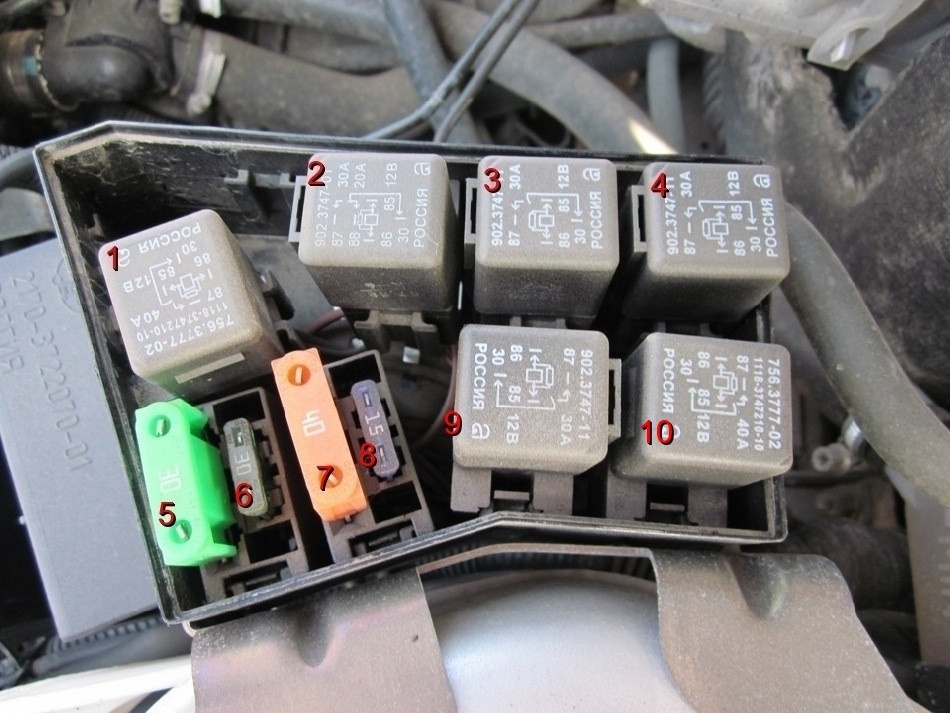
The first block to consider is the norm configuration.
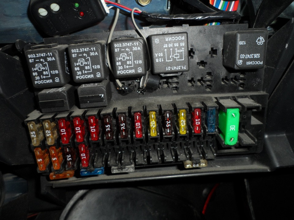
K1 Relay for turning on the electric fan of the radiator of the engine cooling system
K2 Heated rear window relay
Starter enable relay K3
K4 Auxiliary relay (ignition relay)
K5 Space for backup relay
K6 Wiper and washer relay
K7 high beam relay
K8 Horn relay
Alarm relay K9
K10 Spare place for relay
K11 Space for backup relay
K12 Space for backup relay
Circuits protected by fuses
F1(25A) Engine cooling radiator fan
F2(25A) Heated rear window
F3(10A) High beam (starboard side)
F4(10A) High beam (port side)
F5(10A) beep
F6(7,5A) Low beam (port)
F7(7.5A) Dipped beam (starboard side)
F8(10A) Alarm
F9(25A) Heater fan
F10(7.5A) Dashboard (terminal "30"). Internal lighting. Stop signs.
F11(20A) Wiper, heated rear window (control)
F12(10A) Output devices "15
F13(15A) Cigarette lighter
F14(5A) Position light (port side)
F15(5A) Position light (starboard side)
F16(10A) Output "15" ABS
F17(10A) Fog lamp, left
F18(10A) Right fog lamp
F19 (15A) Seat heating
F20(5A) Immobilizer control unit
F21(7.5A) Rear fog lamp
Backup fuse location F22-F30
F31(30A) Power window control unit
F32 Reserved fuse location
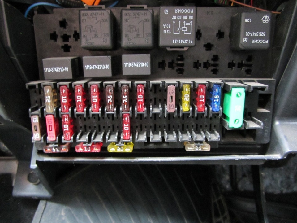
K1 Space for backup relay
K2 Heated rear window relay
Starter enable relay K3
K4 Auxiliary relay
K5 Space for backup relay
K6 Relay for switching on a high-speed wiper (automatic mode
K7 high beam relay
K8 Horn relay
K9 Alarm horn enable relay
K10 Fog lamp relay
K11 Relay for turning on the heating of the front seats
K12 Space for backup relay
Circuits protected by fuses
Reserve F1
F2(25A) Mounting block, heated rear window relay (contacts). Electrical package controller, contact "10" of block XP2. Rear window heating element.
F3(10A) Right headlight, high beam. Instrument cluster, high beam warning light.
F4(10A) Left headlight, high beam.
F5(10A) Mounting block, horn relay
F6(7.5A) Left headlight, low beam.
F7(7.5A) Right headlight, low beam.
F8(10A) Mounting block, horn relay. Sound alarm.
Reserve F9
F10(10A) Instrument cluster, terminal "20". Stoplight switch. Stop signs. Cabin lighting unit. Internal lighting device. Illumination of the threshold of the right front door with a ceiling lamp. Additional brake signal.
F11(20A) Mounting block, wiper high speed relay. Windshield wiper and washer switch, terminal "53a". Wiper and washer switch, terminal "53ah". Rear window heating switch. Mounting block, rear window heating relay (winding). Wiper motor. Rear wiper motor (2171,2172). Windshield washer motor. Rear window washer motor (2171,2172). Airbag control unit, terminal "25".
F12(10A) Instrument cluster, terminal "21". Electrical package controller, contact "9" block X2. Control unit for electromechanical power steering, contact "1" block X2. Reversing light switch reversing lights. Shield of the parking system, terminal "11" and "14".
F13(15A) Cigarette lighter
F14(5A) Side light lamps (left side) Instrument panel, head light indicator License plate lamp Trunk lamp Powertrain control module X2 terminal "12
F15(5A) Position lamps (starboard side) Glove box lighting
F16(10A) Hydraulic unit, terminal "18"
F17(10A) Fog lamp, left
F18(10A) Right fog lamp
F19 (15A) Seat heating switch, contact "1" front seat heating
F20(10A) Recirculation switch (alarm power supply) Mounting block, relay for switching on the dipped beam of headlights and side lights (automatic light control system) Electric heater fan relay Automatic light control switch Wiper and exterior lighting control unit, terminal "3", "11" Controller automatic climate control systems, pin "1" Sensor for automatic windshield cleaning (rain sensor), pin "1"
F21(5A) Light switch, terminal "30" Diagnostic terminal, terminal "16" Clock Climate control system controller, terminal "14"
F22 (20A) Wiper motor (auto mode) Mounting block, wiper on relay and wiper high speed relay, (contacts)
F23 (7,5A) Wiper and outdoor lighting control unit, contact "20"
F24 - F30 Reserved
F31(30A) Power supply controller, terminal "2" of block X1 Power supply controller, terminal "3" of block X1 Driver's door module, terminal "6" Left front door sill lamp
F32 Reserve
K1 Relay for switching on the dipped beam and the position of the headlights (automatic light control system)
K2 Heated rear window relay
Starter enable relay K3
K4 Auxiliary relay
K5 Space for backup relay
K6 Relay for switching on a high-speed wiper (automatic mode
K7 high beam relay
K8 Horn relay
K9 Alarm horn enable relay
K10 Fog lamp relay
K11 Relay for turning on the heating of the front seats
K12 Wiper activation relay (intermittent and automatic)
Circuits protected by fuses
Reserve F1
F2(25A) Mounting block, heated rear window relay (contacts). Electrical package controller, contact "10" of block XP2. Rear window heating element.
F3(10A) Right headlight, high beam. Instrument cluster, high beam warning light.
F4(10A) Left headlight, high beam.
F5(10A) Mounting block, horn relay
F6(7.5A) Left headlight, low beam.
F7(7.5A) Right headlight, low beam.
F8(10A) Mounting block, horn relay. Sound alarm.
Reserve F9
F10(10A) Instrument cluster, terminal "20". Stoplight switch. Stop signs. Cabin lighting unit. Internal lighting device. Illumination of the threshold of the right front door with a ceiling lamp. Additional brake signal.
F11(20A) Mounting block, wiper high speed relay. Windshield wiper and washer switch, terminal "53a". Wiper and washer switch, terminal "53ah". Rear window heating switch. Mounting block, rear window heating relay (winding). Wiper motor. Rear wiper motor (2171,2172). Windshield washer motor. Rear window washer motor (2171,2172). Airbag control unit, terminal "25".
F12(10A) Instrument cluster, terminal "21". Electrical package controller, contact "9" block X2. Control unit for electromechanical power steering, contact "1" block X2. Reversing light switch reversing lights. Shield of the parking system, terminal "11" and "14".
F13(15A) Cigarette lighter
F14(5A) Side light lamps (left side) Instrument panel, head light indicator License plate lamp Trunk lamp Powertrain control module X2 terminal "12
F15(5A) Position lamps (starboard side) Glove box lighting
F16(10A) Hydraulic unit, terminal "18"
F17(10A) Fog lamp, left
F18(10A) Right fog lamp
F19 (15A) Seat heating switch, contact "1" front seat heating
F20(10A) Recirculation switch (alarm power supply) Mounting block, relay for switching on the dipped beam of headlights and side lights (automatic light control system) Electric heater fan relay Automatic light control switch Wiper and exterior lighting control unit, terminal "3", "11" Controller automatic climate control systems, pin "1" Sensor for automatic windshield cleaning (rain sensor), pin "1"
F21(5A) Light switch, terminal "30" Diagnostic terminal, terminal "16" Clock Climate control system controller, terminal "14"
F22 (20A) Wiper motor (auto mode) Mounting block, wiper on relay and wiper high speed relay, (contacts)
F23 (7,5A) Wiper and outdoor lighting control unit, contact "20"
F24 - F30 Reserved
F31(30A) Power supply controller, terminal "2" of block X1 Power supply controller, terminal "3" of block X1 Driver's door module, terminal "6" Left front door sill lamp
Reserve F32
See also: turn signals as running lights
There is also an additional mounting block and a block of the air conditioning system.
Power fuse F1 (30 A) electronic engine management (ECM) power supply circuits
F2 fuse (60 A) for the power supply circuit of the electric fan of the engine cooling system (power circuit), additional relay (ignition relay), heated rear window, electrical equipment controller
F3 (60A) Engine Cooling Fan Power Circuit Fuse (Relay Control Circuit), Horn, Alarm, Ignition Switch, Instrument Cluster, Interior Lights, Stop Lamp, Cigarette Lighter
F4, F6 (60 A) fuses for the generator power circuit;
Fuse F5 (50 A) for the power steering circuit of the electromechanical power steering
1 - fuse for the power supply circuit of the right electric fan (30 A);
2 - fuse for the power supply circuit of the left electric fan (30 A).
3 - electric fan relay on the right;
4 - additional relay (sequential switching on of electric ventilation
left and right lators);
5 – left electric fan relay;
6 - fuse for the power supply circuit of the electric fan of the heater (40 A);
7 - fuse for the compressor power circuit (15 A);
8 - heater electric fan relay;
9 - compressor relay.