Fuses and relay Toyota Kaldina
Content
The second generation Toyota Caldina T21 was produced in 1997, 1998, 1999, 2000, 2001 and 2002 as a station wagon with petrol and diesel engines. During this time, the model has been redesigned. The most popular models are marked T 210/211/215. In this article you can find information about the location of electronic control units and a description of fuses and relays for Toyota Kaldina T21x with block diagrams and photo examples. Separately, we look at the cigarette lighter fuse.

The number of elements in the blocks and their location may differ from those shown and depend on the year of manufacture and the level of equipment.
Blocks in the salon
Location
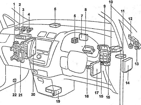
The general arrangement of blocks in the cabin

Goal
- 11 - left side SRS sensor
- 12 - DC / AC converter
- 13 - switching relay (until 10.1997)
- 14 - electrohatch relay
- 15 - right side SRS sensor
- 16 - electronic control unit of the navigation system (since 12.1999)
- 17 - rear wiper relay
- 18 - electronic engine control unit
- 19 - central mounting block
- 20 - door lock control relay
- 21 - built-in relay
- 22 - relay block No. 1
- 23 - relay connector for connecting additional electrical equipment
- 24 - fuse box
- 25 - right bracket for fastening connectors
- 26 - mounting block under the dashboard in the cabin
- 27 - windshield heating relay (brush heater)
- 28 - headlight corrector relay (since 12.1999)
- 29 - automatic transmission selector lock control unit
- 30 - deceleration sensor (ABS) (models with VSC)
- 31 - deceleration sensor (ABS, 4WD models); side motion sensor (models with VSC)
- 32 - central SRS sensor
- 33 - heater relay
- 34 - left bracket for mounting connectors
- 35 - fuel pump relay
- 36 - fuse block (ZS-TE from 12.1999)
- 37 - Electronic control unit ABS, TRC and VSC.
Fuse box
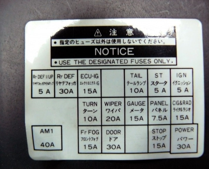
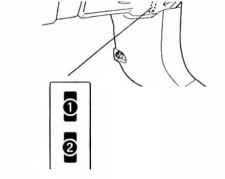
In the passenger compartment, the fuse box is located under the instrument panel on the driver's side, behind a protective cover.

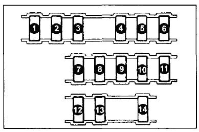
Block Deck Diagram Example
scheme
Description
| а | 5A DEFOG / IDLE-UP - Idle boost system, electronic engine control unit |
| two | 30A DEFOG - rear window defroster |
| 3 | 15A ECU - IG - anti-lock brakes, shift lock system |
| 4 | 10A TAIL - Front and rear markers, license plate lights |
| 5 | 5A STARTER - Starter, engine control unit |
| 6 | 5A IGNITION - ignition, electronic engine control unit |
| 7 | 10A TURN - direction indicators |
| 8 | 20A WIPER - Windshield wiper and washer |
| 9 | 15A METER - Instrument Cluster |
| 10 | PANEL 7.5A - Dashboard lights and switches |
| 11 | 15A CARINITOR/RADIO - Power side mirrors, cigarette lighter, clock, radio |
| 12 | 15A FOG LIGHTS - Front fog lights |
| thirteen | DOOR 30A - Central locking |
| 14 | 15A STOP brake lights |
The fuse responsible for the cigarette lighter is number 11 at 15A.
Some relays can be connected to the back of the unit.
- Main power relay
- Measurement relay
- Rear heater relay
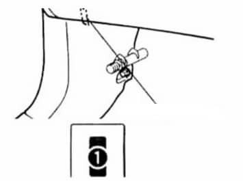
Additional Items
Separately, closer to the left drain, you can connect some additional fuses.
scheme
designation
- 15A FR DEF - Heated wipers
- 15A ACC SOCKET - Additional sockets
And on the left side panel: 1 20A F / HTR - fuel heating
Blocks under the hood
Location
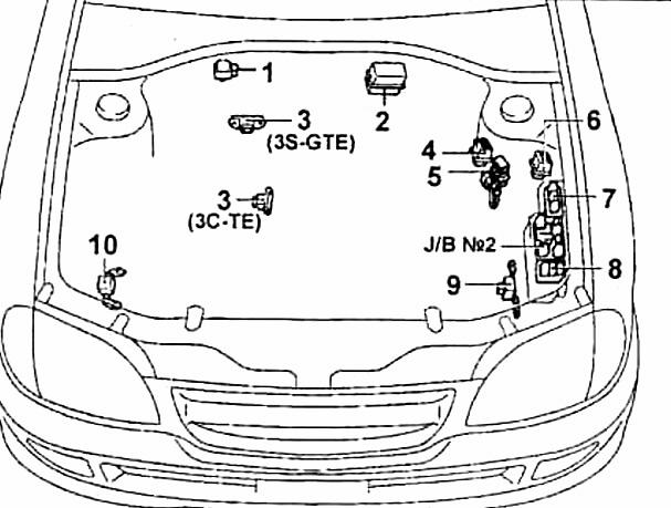
General arrangement of blocks under the hood
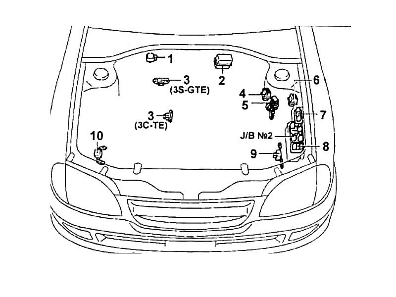
Description
- vacuum sensor in the vacuum brake booster (7A-FE, 3S-FE)
- relay block VSK
- boost pressure sensor
- candle light is on
- fuel pump resistor
- fuel pump control relay
- relay block No. 2
- block of fusible inserts
- front left SRS sensor
- front right SRS sensor
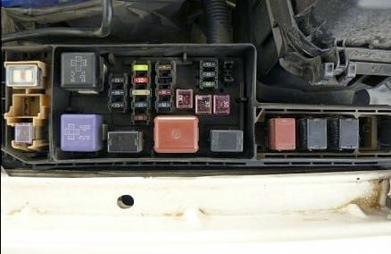
Fuse and relay box
The main fuse and relay box is located on the left side of the engine compartment, next to the battery. There are several options for its implementation.
Photo - example
scheme
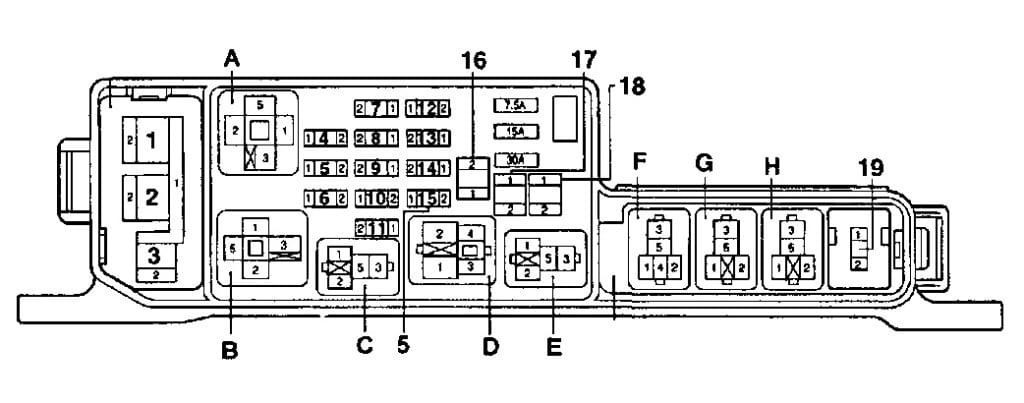
transcribed
| Relay A - relay No. 1 of the e / engine cooling system fan, B - starter relay, C - horn relay, D - headlight relay, E - injection system relay, F - relay No. 2 of the e / engine cooling system fan, G - relay No. 3 fan of the cooling system e / dv, H - air conditioner relay; |
| fusible links 1 - ALT 100A (120A for 3S-FSE engines), 2 - ABS 60A, 3 - HTR 40A; |
Circuit breakers
|