Checking the ignition with an oscilloscope
Content
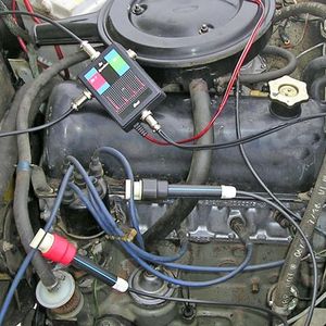
The most advanced method for diagnosing the ignition systems of modern cars is carried out using motor-tester. This device shows the high voltage waveform of the ignition system, and also provides real-time information on ignition pulses, breakdown voltage value, burning time and spark strength. At the heart of the motor tester lies digital oscilloscope, and the results are displayed on the screen of a computer or tablet.
The diagnostic technique is based on the fact that any failure in both the primary and secondary circuits is always reflected in the form of an oscillogram. It is affected by the following parameters:
Checking the ignition with an oscilloscope
- ignition timing;
- crankshaft rotation frequency;
- throttle opening angle;
- boost pressure value;
- composition of the working mixture;
- other reasons.
Thus, with the help of an oscillogram, it is possible to diagnose breakdowns not only in the ignition system of a car, but also in its other components and mechanisms. Ignition system breakdowns are divided into permanent and sporadic (occurring only under certain operating conditions). In the first case, a stationary tester is used, in the second, a mobile one used while the car is moving. Due to the fact that there are several ignition systems, the received oscillograms will give different information. Let's consider these situations in more detail.
Classic ignition
Consider specific examples of faults using the example of oscillograms. In the figures, the graphs of the faulty ignition system are indicated in red, respectively, in green - serviceable.
Open after capacitive sensor
Break in the high-voltage wire between the installation point of the capacitive sensor and the spark plugs. In this case, the breakdown voltage increases due to the appearance of an additional spark gap connected in series, and the spark burning time decreases. In rare cases, the spark does not appear at all.
It is not recommended to allow prolonged operation with such a breakdown, since it can lead to a breakdown of the high-voltage insulation of the ignition system elements and damage to the power transistor of the switch.
Wire break in front of the capacitive sensor
Breakage of the central high-voltage wire between the ignition coil and the installation point of the capacitive sensor. In this case, an additional spark gap also appears. Because of this, the voltage of the spark increases, and the time of its existence decreases.
In this case, the reason for the distortion of the oscillogram is that when a spark discharge burns between the candle electrodes, it also burns in parallel between the two ends of the broken high-voltage wire.
The resistance of the high voltage wire between the installation point of the capacitive sensor and the spark plugs has been greatly increased.
Increased resistance of the high voltage wire between the installation point of the capacitive sensor and the spark plugs. The resistance of a wire can be increased due to oxidation of its contacts, aging of the conductor, or use of a wire that is too long. Due to the increase in resistance at the ends of the wire, the voltage drops. Therefore, the shape of the oscillogram is distorted so that the voltage at the beginning of the spark is much greater than the voltage at the end of combustion. Because of this, the duration of the burning of the spark becomes shorter.
breakdowns in high-voltage insulation are most often its breakdowns. They can happen between:
- high-voltage output of the coil and one of the outputs of the primary winding of the coil or "ground";
- high-voltage wire and internal combustion engine housing;
- ignition distributor cover and distributor housing;
- distributor slider and distributor shaft;
- “cap” of a high-voltage wire and an internal combustion engine housing;
- wire tip and spark plug housing or internal combustion engine housing;
- the central conductor of the candle and its body.
usually, in idle mode or at low loads of the internal combustion engine, it is quite difficult to find insulation damage, including when diagnosing an internal combustion engine using an oscilloscope or a motor tester. Accordingly, the motor needs to create critical conditions in order for the breakdown to manifest itself clearly (starting the internal combustion engine, abruptly opening the throttle, operating at low revs at maximum load).
After the occurrence of a discharge at the place of insulation damage, current begins to flow in the secondary circuit. Therefore, the voltage on the coil decreases, and does not reach the value required for a breakdown between the electrodes on the candle.
On the left side of the figure, you can see the formation of a spark discharge outside the combustion chamber due to damage to the high-voltage insulation of the ignition system. In this case, the internal combustion engine operates with a high load (regassing).
The surface of the spark plug insulator is heavily soiled on the combustion chamber side.
Pollution of the spark plug insulator on the combustion chamber side. This can be due to deposits of soot, oil, residues from fuel and oil additives. In these cases, the color of the deposit on the insulator will change significantly. You can read information about the diagnosis of internal combustion engines by the color of soot on a candle separately.
Significant contamination of the insulator can cause surface sparks. Naturally, such a discharge does not provide reliable ignition of the combustible-air mixture, which causes misfiring. Sometimes, if the insulator is contaminated, flashovers may occur intermittently.
The form of high voltage pulses generated by an ignition coil with an interturn breakdown.
Breakdown of interturn insulation of the ignition coil windings. In the event of such a breakdown, a spark discharge appears not only on the spark plug, but also inside the ignition coil (between the turns of its windings). It naturally takes away energy from the main discharge. And the longer the coil is operated in this mode, more energy is lost. At low loads on the internal combustion engine, the described breakdown may not be felt. However, with an increase in the load, the internal combustion engine may begin to “troit”, lose power.
Gap between spark plug electrodes and compression
The gap between the spark plug electrodes is reduced. The internal combustion engine is idling without load.
The mentioned gap is selected for each car individually, and depends on the following parameters:
- the maximum voltage developed by the coil;
- insulation strength of system elements;
- maximum pressure in the combustion chamber at the moment of sparking;
- the expected service life of the candles.
The gap between the electrodes of the spark plug is increased. The internal combustion engine is idling without load.
Using an oscilloscope ignition test, you can find inconsistencies in the distance between the spark plug electrodes. So, if the distance has decreased, then the probability of ignition of the fuel-air mixture is reduced. In this case, breakdown requires a lower breakdown voltage.
If the gap between the electrodes on the candle increases, then the value of the breakdown voltage increases. Therefore, in order to ensure reliable ignition of the fuel mixture, it is necessary to operate the internal combustion engine at a small load.
Please note that prolonged operation of the coil in a mode where it produces the maximum possible spark, firstly, leads to its excessive wear and early failure, and secondly, this is fraught with insulation breakdown in other elements of the ignition system, especially in high-voltage . there is also a high probability of damage to the elements of the switch, namely, its power transistor, which serves the problematic ignition coil.
Low compression. When checking the ignition system with an oscilloscope or a motor tester, low compression in one or more cylinders can be detected. The fact is that at low compression at the time of sparking, the gas pressure is underestimated. Accordingly, the gas pressure between the electrodes of the spark plug at the time of sparking is also underestimated. Therefore, a lower voltage is needed for breakdown. The shape of the pulse does not change, but only the amplitude changes.
In the figure on the right, you see an oscillogram when the gas pressure in the combustion chamber at the time of sparking is underestimated due to low compression or due to a large value of the ignition timing. The internal combustion engine in this case is idling without load.
DIS ignition system
High-voltage ignition pulses generated by healthy DIS ignition coils of two different ICEs (idle without load).
The DIS (Double Ignition System) ignition system has special ignition coils. They differ in that they are equipped with two high-voltage terminals. One of them is connected to the first of the ends of the secondary winding, the second - to the second end of the secondary winding of the ignition coil. Each such coil serves two cylinders.
In connection with the described features, the verification of ignition with an oscilloscope and the removal of an oscillogram of the voltage of high-voltage ignition pulses using capacitive DIS sensors occur differentially. That is, it turns out the actual reading of the oscillogram of the output voltage of the coil. If the coils are in good condition, then damped oscillations should be observed at the end of combustion.
To carry out diagnostics of the DIS ignition system by primary voltage, it is necessary to alternately take voltage waveforms on the primary windings of the coils.
Picture Description:
Voltage waveform on the secondary circuit of the DIS ignition system
- Reflection of the moment of the beginning of energy accumulation in the ignition coil. It coincides with the opening moment of the power transistor.
- Reflection of the transition zone of the switch to the current limiting mode in the primary winding of the ignition coil at a level of 6 ... 8 A. Modern DIS systems have switches without a current limiting mode, so there is no zone of a high-voltage pulse.
- Breakdown of the spark gap between the electrodes of the spark plugs served by the coil and the start of spark burning. Coincides in time with the moment of closing the power transistor of the switch.
- Spark burning area.
- The end of spark burning and the beginning of damped oscillations.
Picture Description:
Voltage waveform at the control output DIS of the ignition coil.
- The moment of opening the power transistor of the switch (the beginning of energy accumulation in the magnetic field of the ignition coil).
- The zone of transition of the switch to the current limiting mode in the primary circuit when the current in the primary winding of the ignition coil reaches 6 ... 8 A. In modern DIS ignition systems, the switches do not have a current limiting mode, and, accordingly, there is no zone 2 on the primary voltage waveform missing.
- The moment of closing the power transistor of the switch (in the secondary circuit, in this case, a breakdown of the spark gaps appears between the electrodes of the spark plugs served by the coil and the spark begins to burn).
- Reflection of a burning spark.
- Reflection of the cessation of spark burning and the beginning of damped oscillations.
Individual ignition
Individual ignition systems are installed on most modern gasoline engines. They differ from classical and DIS systems in that each spark plug is serviced by an individual ignition coil. usually, the coils are installed just above the candles. Occasionally, switching is done using high-voltage wires. Coils are of two types − compact и rod.
When diagnosing an individual ignition system, the following parameters are monitored:
- the presence of damped oscillations at the end of the spark burning section between the electrodes of the spark plug;
- the duration of energy accumulation in the magnetic field of the ignition coil (usually, it is in the range of 1,5 ... 5,0 ms, depending on the model of the coil);
- the duration of the spark burning between the electrodes of the spark plug (usually, it is 1,5 ... 2,5 ms, depending on the model of the coil).
Primary voltage diagnostics
To diagnose an individual coil by primary voltage, you need to view the voltage waveform at the control output of the primary winding of the coil using an oscilloscope probe.
Picture Description:
Oscillogram of the voltage at the control output of the primary winding of a serviceable individual ignition coil.
- The moment of opening the power transistor of the switch (the beginning of energy accumulation in the magnetic field of the ignition coil).
- The moment of closing the power transistor of the switch (the current in the primary circuit is abruptly interrupted and a breakdown of the spark gap appears between the electrodes of the spark plug).
- The area where the spark burns between the electrodes of the spark plug.
- Damped vibrations that occur immediately after the end of the spark burning between the electrodes of the spark plug.
In the figure on the left, you can see the voltage waveform at the control output of the primary winding of a faulty individual short circuit. A sign of a breakdown is the absence of damped oscillations after the end of the spark burning between the spark plug electrodes (section “4”).
Secondary voltage diagnosis with capacitive sensor
The use of a capacitive sensor to obtain a voltage waveform on the coil is more preferable, since the signal obtained with its help more accurately repeats the voltage waveform in the secondary circuit of the diagnosed ignition system.
Oscillogram of the high voltage pulse of a healthy compact individual short circuit, obtained using a capacitive sensor
Picture Description:
- The beginning of energy accumulation in the magnetic field of the coil (coincides in time with the opening of the power transistor of the switch).
- Breakdown of the spark gap between the electrodes of the spark plug and the start of spark burning (at the moment the power transistor of the switch closes).
- The spark burning area between the spark plug electrodes.
- Damped oscillations that occur after the end of the spark burning between the electrodes of the candle.
Oscillogram of the high voltage pulse of a healthy compact individual short circuit, obtained using a capacitive sensor. The presence of damped oscillations immediately after the breakdown of the spark gap between the spark plug electrodes (the area is marked with the symbol “2”) is a consequence of the design features of the coil and is not a sign of a breakdown.
Oscillogram of the high voltage pulse of a faulty compact individual short circuit, obtained using a capacitive sensor. A sign of a breakdown is the absence of damped oscillations after the end of the spark burning between the electrodes of the candle (the area is marked with the symbol “4”).
Secondary voltage diagnostics using an inductive sensor
An inductive sensor when performing diagnostics on the secondary voltage is used in cases where it is impossible to pick up a signal using a capacitive sensor. Such ignition coils are mainly rod individual short circuits, compact individual short circuits with a built-in power stage for controlling the primary winding, and individual short circuits combined into modules.
Oscillogram of a high voltage pulse of a healthy rod individual short circuit, obtained using an inductive sensor.
Picture Description:
- The beginning of energy accumulation in the magnetic field of the ignition coil (coincides in time with the opening of the power transistor of the switch).
- Breakdown of the spark gap between the electrodes of the spark plug and the start of spark burning (the moment the power transistor of the switch closes).
- The area where the spark burns between the electrodes of the spark plug.
- Damped vibrations that occur immediately after the end of the spark burning between the electrodes of the spark plug.
Oscillogram of the high voltage pulse of a faulty rod individual short circuit, obtained using an inductive sensor. A sign of failure is the absence of damped oscillations at the end of the spark burning period between the spark plug electrodes (the area is marked with the symbol “4”).
Oscillogram of the high voltage pulse of a faulty rod individual short circuit, obtained using an inductive sensor. A sign of failure is the absence of damped oscillations at the end of the spark burning between the spark plug electrodes and a very short spark burning time.
Hack and predictor Aviator
Diagnostics of the ignition system using a motor tester is the most advanced troubleshooting method. With it, you can identify breakdowns also at the initial stage of their occurrence. The only drawback of this diagnostic method is the high price of the equipment. Therefore, the test can only be carried out at specialized service stations, where there are appropriate hardware and software.