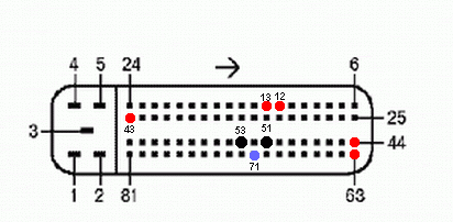
Pinout January 7.2
In this material, we will give a detailed description of the ECU pinout January 7.2.
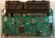
First, let's figure out the pin layout on the connector. Below is an image with numbered pins.
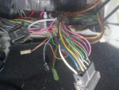
ECU pinout diagram January 7.2
| Pin | Connection |
| 1 | 21114 - Not used / (for 16 cells) 21124 - Ignition coil 2 cylinders. |
| 2 | 21114 - Ignition 2-3. Control of the primary winding of the ignition coil, act. level is low. / (for 16 classes) 21124 - Ignition coil 3 cylinders. |
| 3 | Ignition circuit weight |
| 4 | 21114 - Not used / (for 16 classes) 21124 - Ignition coil 4 cylinders. |
| 5 | 21114 - Ignition 1-4. Control of the primary winding of the ignition coil, act. level is low. / (for 16 classes) 21124 - Ignition coil 1 cylinders. |
| 6 | Injector 2. Active level low |
| 7 | Injector 3. Active level low |
| 8 | Tachometer output. |
| 9 | Not used |
| 10 | Fuel consumption signal |
| 11 | Not used |
| 12 | Battery, terminal 30 of the ignition lock. |
| 13 | Food. Terminal 15 of the ignition switch |
| 14 | Main relay |
| 15 | Contact “A” DPKV |
| 16 | DPDZ |
| 17 | DPDZ weight / (for EURO-3 systems with 2 oxygen sensors) Weight DPDZ, DND |
| 18 | Input - oxygen sensor |
| 19 | Input - knock sensor |
| 20 | Knock sensor weight |
| 21 | Not used |
| 22 | Not used |
| 23 | Not used |
| 24 | Not used |
| 25 | Bosch only - high current output, redundant |
| 26 | Bosch only - high current output, redundant |
| 27 | Injector 1. Active level low |
| 28 | Not used / (for EURO-3 systems with 2 oxygen sensors) Heater control output DK2 |
| 29 | Not used / (for EURO-3 systems with 2 oxygen sensors) Engine cooling fan control output 2 |
| 30 | Not used |
| 31 | CE lamp, act. level low |
| 32 | Power supply TPS / (for EURO-3 systems with 2 oxygen sensors) Power supply DPDZ, DND |
| 33 | Power supply for the DMRV |
| 34 | DPKV input, contact “B” |
| 35 | DTOZH weight / (for EURO-3 systems with 2 oxygen sensors) Mass of DTOZh, DMRV, 1 DK (UDC), 2 DK (DDK) |
| 36 | Mass of mass air flow sensor |
| 37 | Signal input from mass air flow sensor |
| 38 | Not used |
| 39 | Signal input from DTOZH |
| 40 | Intake air temperature sensor signal input |
| 41 | Not used |
| 42 | Not used / (for EURO-3 systems with 2 oxygen sensors) DND signal input |
| 43 | Not used |
| 44 | Onboard voltage input at the output of the main relay |
| 45 | Phase sensor power output |
| 46 | Canister purge valve control output |
| 47 | Injector 4. Active level low |
| 48 | Oxygen sensor heater control output |
| 49 | Not used |
| 50 | Auxiliary starter relay control output |
| 51 | Controller weight |
| 52 | Not used |
| 53 | Controller weight |
| 54 | Not used |
| 55 | Not used / (for EURO-3 systems with 2 oxygen sensors) DK2 signal input (DDC) |
| 56 | Not used |
| 57 | Coding input for calibration data options. The controller memory can contain 2 sets of calibration data, switching is performed by shorting to ground. |
| 58 | Not used |
| 59 | Speed sensor |
| 60 | Not used |
| 61 | Output stage weight |
| 62 | Not used |
| 63 | Onboard voltage input at the output of the main relay |
| 64 | Output “D” IAC |
| 65 | Output “C” IAC |
| 66 | Output “B” IAC |
| 67 | Output “A” IAC |
| 68 | Engine cooling fan relay control output, act. level - low |
| 69 | Air conditioning relay control output, act. level - low |
| 70 | Fuel pump relay control output, act. level - low |
| 71 | K line |
| 72 | Not used |
| 73 | Not used |
| 74 | Not used |
| 75 | Input request to turn on the air conditioner, act. level - high |
| 76 | Power steering request input, act. level - high |
| 77 | Not used |
| 78 | Not used |
| 79 | Phase sensor signal input |
| 80 | Output stage weight |
| 81 | Not used |
