
Unloader valve Maz 5440
Consider malfunctions of the MAZ brake system.
Possible malfunctions of the MAZ brake system
Table 13. Possible malfunctions of braking devices and their elimination through the water separator Leakage from stationary interfaces with the bodyIncomplete release of the brake chambers (presence of excessive air pressure) Air leakage from the vent holeAir leakage through the vent hole when the lever is pressed from one receiver (through the condensate drain valve) the air pressure in the other receiver dropsSemi-trailer brake control valve with a single-wire actuator fish into the atmosphere. When braking, the air continues to escape below deck into the atmosphere The air pressure in the semi-trailer receivers deviates from the norm 0,9-9 MPa (2-0,47 kgf / cm 0,52) Air leakage through the atmospheric hole in the bottom cover Reverse-acting brake valve with air leakage due to the atmospheric opening in one of the fixed positions of the handle Air leakage from under the tap cover The drive handle is not fixed in the extreme positions by manual override Air leakage through the breather when braking with a brake valve (pedal) Spontaneous braking of the semi-trailer, accompanied by air suction from the brake valve breather Air leakage through the brake valve breatherMAZ with adsorber 4,7-5,2
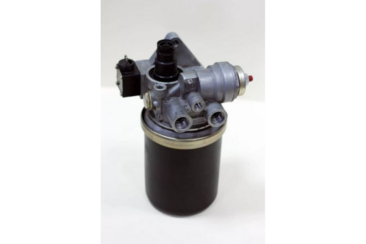
Air pressure regulator MAZ 8043-3512010 with an adsorber. A pressure regulator with an adsorber or an air pressure regulator with a dryer 8043-3512010 performs several functions in the pneumatic brake system of a MAZ vehicle. All the main units of the pressure regulator with a dryer are assembled in one element, ensuring its operation and control of the pneumatic system: pressure regulator, safety and check valve, heater, filter with a dryer 432.410.2227, silencer. The principle of operation of the MAZ pressure regulator with a dryer is very simple. From the compressor, the air enters through the channel into the regulator body and the filter or adsorbent cartridge. The adsorbent precipitates moisture, and the filter retains various impurities. After drying, compressed air enters the pressure regulator and safety valve, from where it enters the pneumatic system of the MAZ vehicle or is released into the atmosphere. Since the release of air is accompanied by noise, a silencer (a small plastic mushroom) is installed on the regulator. In the cold season, at temperatures below +7 C, the heating element is turned on in the dryer. The heating element prevents moisture from freezing in the dryer. The air pressure regulator 8043-3512010 is connected by a pneumatic system to a pneumatic compressor (air supply), a four-circuit protective valve 100-3515410 and a regeneration receiver 64226-3513015, installed on the right side of the vehicle frame. The dryer cartridge should be changed once a year. The pressure regulator with a dryer 8043-3512010 is installed on MAZ vehicles of models 5440, 6430, 5340, 6312, 5550, 6501, 6516 and their modifications, as well as on MAZ vehicles of models 5432, 5433, 5434, 6422, 6425, 5336, 5337, 6303 , 5551, 5516 and their modifications after 2003. In the following diagram, the air pressure regulator 8043-3512010 with a position adsorber No. 5,6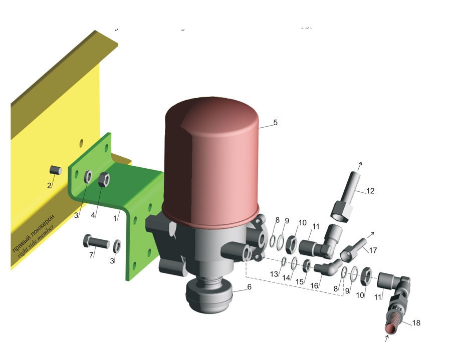
MAZ pressure regulator: possible causes of breakdowns The performance and reliability of the brake system of a car is the key to its safe operation. Therefore, the spare parts used in the repair and maintenance process must be of high quality. When operating MAZ trucks, it is recommended to install only original spare parts purchased from reliable suppliers.
Any MAZ vehicle initially has several brake systems: working, parking, spare, auxiliary. In addition, the brakes installed on the semi-trailer can be activated additionally.
Before buying a new truck in Khabarovsk or the Khabarovsk Territory, consult with Transservice managers who will help you choose a model of equipment according to your preferences and tasks! Among the elements that directly affect the operation of the brake system is a pressure regulator that maintains optimal pressure in the pneumatic system car. At MAZ, the regulator also performs the function of a dehumidifier, removing moisture from the air injected into the system by the compressor. There may be several versions of the unit, for example, with heat output. Among other options, the presence or absence of an adsorber, the supply voltage of electric heating, etc. The use of regulators with an adsorber is necessary for vehicles in which the brake system operates at a pressure value in the range of 6,5-8 kgf / cm2. During operation, it periodically discharges air into the atmosphere, preventing the occurrence of excess pressure. When the unit is turned on, the pressure in the system is within 0,65 MPa, and when it is turned off, its value drops to 0,8 MPa. In cases of pressure increase to 1,0-1,35 MPa, excess air is removed through the safety valve. The principle of operation of such a pressure regulator is extremely simple. Under standard conditions, the compressor sucks air into the housing, from where it is sent through the check valve to the air cylinders. The regulator was originally designed to work in harsh conditions, so it can remain operational at low temperatures down to -45 degrees and at a temperature of 80 degrees. The rated power of the device is 125 watts. Most models operate on 24 V, but there are also versions designed for 12 V. The heater (if any) is connected to the operation at a temperature below +7 degrees and is turned off when the temperature reaches +35 degrees. Source 6.2.1. Brake systems. Pneumatic brake drive. Maintenance The MAZ brake system (TS) serves to ensure safety when driving a truck and fixing it in the parking lot. Structurally, it is made in the form of four independent systems: working, parking, spare and auxiliary. In normal driving mode, a working machine is used, however, in the event of an accident or emergency braking, all brakes are activated. Device The brake system circuit is based on the principle of independent action on the front and rear axle drive mechanisms. The pneumatic actuator used on MAZ vehicles consists of the following elements:
- compressor;
- compressed air cylinders (receiver);
- pneumatic lines and control devices;
- braking mechanisms.
The vehicle can be equipped with a single or double cylinder compressor. The latter is used in tractors (road trains). Compressed air is supplied through pneumatic hoses to the receivers. In the car, depending on the model, 3 or 4 air springs of various capacities can be used. Each pair of wheels (axle) has its own receiver: front and middle - 40 liters each, rear - 20 liters. The parking system is equipped with a separate 20 liter bottle.
The device of the MAZ brake system provides for the installation of drum brakes.
Here, braking occurs due to friction that occurs when fitting the pads located in the fixed caliper to the inner surface of the movable (rotating) drum. It is made of cast iron with a diameter of 420 mm and a working surface width of 160 mm. The brake pads are made of steel. Friction linings made of asbestos-free material are installed on top. The gap between the shoes and the surface of the drum is regulated by a lever with a built-in automatic regulator. The front wheel brakes are actuated by diaphragm brake chambers (TC). On the rear axles, the force on the pads is transmitted through spring energy accumulators. Control air is supplied to the actuators by a brake valve through a four-circuit valve. This activates the brakes on all wheels at the same time. If there is a trailer, to prevent its collision with the tractor, a trailer brake control valve is installed, which allows you to apply the brakes somewhat faster than on the tractor. drivers who do not have a special electrical engineering education. At the same time, Minsk-made cars have many systems that are only slightly inferior in complexity to electrical devices.
Such complex systems include the MAZ braking system. In addition, its main difficulty lies in the fact that it consists of several subsystems at once, different in structure, specific purpose (in some cases, subsystems perform the functions of their “brothers”) and principles of interaction with other subsystems. The standard scheme of MAZ brakes includes the following subgroups: - working; - auxiliary; - replacement; – parking. Using the latter as an example, we will talk about what needs to be done in order to avoid systemic problems and avoid failures ... The MAZ handbrake and its drive do not require special care, but you need to remember a few rules: • be sure to periodically check the drive cables and swivel joints for signs of wear and, if any, replace them immediately; • avoid loose fastenings and contamination of joints; • when lubricating, strictly follow the manufacturer's recommended lubrication table, but do not forget to make adjustments in case of deviations in operating conditions; • before each sortie, also make sure that the MAZ parking brake works smoothly and that it is able to keep the car within the specified limits. road with a slope of 5335. Only correctly adjusted and absolutely maintainable MAZ brakes can cope with this task. Therefore, one more thing should be added to the listed rules: for preventive and forced replacement of parts of the brake system, use only high-quality spare parts and components. Exactly what ours offers you - one of the best manufacturers of spare parts for Minsk and not only equipment. In addition, we are the best not only because all our products are of the highest quality, but also due to very affordable prices that can please any MAZ owner (driver). 1-5336 valve brake hose 3519210 1-5336 valve brake hose 3519210 2-6422-3506094 pipes 2 6422 exhaust valve 3506094 3-64229- 3506283 PIPE 10 4-13.3515310 Lifter with lever assy. 5 Pipe 64229 3506282-10 Pipe 7 C100-3514008 PNEUMATIC8 WATER SIPER SIPER PEAPER 6422 3506142-10-9 hose 5336-3509012 Dressing regulator Knot 11 64226-3506316-11 hose 40 3721000-1.3511010-13 LENGN 5336 Hose 3506187 01-14 100 3512010-15-6422 Hose 3506085 01 Four-way valve 15 6422-3506085-01 Tube 15 6422-3506085-01-15-606285 O-ring 31 16-100-3506085-01-3506 O-ring 1000 -18 Cylinder Engine stop 64229 3506148-20 Cylinder 19 008-011 -19 Tube 2 3-20-012 A016-25 2 3-21 receiver 100 3570110-22 TUBE 100 3570210-23 Tube 5551 3570234-01-24 Tube 6303 3513015-10 TUP 40 280ENT 25 Control valve Trailer 5336 353015-25-5336 Tube 353015 29-64229-3506154 Tube Knot 29 64229-35062440 TUBE 20 30-53362-3506178 TUBE 31-64221 Tube 3506180 20 32 5336 3506319 33 943.002.521.0 34 64229 3506248 20 35 54323 2006146AR -10 TUBE 36 53362-3506289 TUBE 37 64229-3506183 TUBE 10 38-64229 Ускорение клапана 3506243 20-39 TUBE 64229 35063-4 Задняя камера тормоза 030563 5-41 задняя тормозная камера 53362 3506337-42-B5361 Adjuster Force 3506136 44-53362 Connecting head 3506188 45-11 Connecting head 3518010 47-53361-3506158-48-5336 sealing ring 3519200 48 Washer 5336 3519200 49n 500 3506060 Washer 2 51 64226-3521110 CRC 51 64226 Nipple 3521110 52 Bolt M014 018 Nut M25-2N 3 53-375960 53 375960-6 Tube55 Brake valve 250159 16-56-63031 Tube 3521050 57-401509-58 Tube 201497 10-6 Crane brake 25 59.
- low braking efficiency;
- uneven braking of the right and left wheels;
- blocking of service or parking brakes (brake wedge);
- increase the travel of the handbrake lever.
An increase in the braking distance can occur due to a large gap between the shoes and the brake drum (TB), due to wear of the shoes or insufficient return of the rods at low pressure in the pneumatic system. If such a malfunction appeared after a repair associated with replacing the pads, then there is a high probability of oiling of the friction material or the inner surface of the fuel tank. in the spacers in the brake shoe block. Slow braking is usually due to a broken or stuck return spring in the brake cylinder. The cause of such a defect may be incorrect adjustment of the brake pedal. Therefore, the brake valve lever does not reach the stop. Due to the breakage of the pressure springs of the brake pads, spontaneous braking may occur, and when driving, a characteristic knock will be heard in the wheel. When the truck is moving with a trailer, the braking of the trailer may be delayed. This is due to improper installation of the adjusting ring on the brake valve. The same malfunction is typical for the piston lock in the air distributor of the trailer. It must be remembered that a steering failure will only lead to a loss of control of the machine, and a vehicle failure will make it impossible to stop it, which will inevitably end in an accident. air pumped by the processor and stored in tanks. Simply put, the air from the tanks is pumped into the compressor. When you press the brake pedal, the force is transferred to the valve, which creates pressure in the brake chambers, actuated by the brake lever. When the driver releases the pedal, the lever weakens and the process stops. Modern tractors are equipped with Wabco, Knorr-Bremse, Haldex systems. Wabco has proven itself to be a reliable and efficient system thanks to ABS. Two-axle semi-trailers are completed with three-axle semi-trailers with anti-blocking system 2S/2M - 4S/3M. Regardless of the model and purpose, an energy accumulator is installed on each semi-trailer. Wabco manufactures diagnostic tools and software that allow you to detect defects and perform tests. How to Remove a Brake Drum Both the brake pads and the inner surface of the drum wear out during the operation of the car. As a result, braking efficiency is reduced. In this case, it is necessary to disassemble the drum and replace the pads. The disassembly work is not difficult, but it will require some physical effort, since the parts are heavy. To remove the brake drum, follow these steps:
- install the machine on a flat surface and fix it from possible movements;
- lift the wheel;
- unscrew the nuts and remove it;
- screw 3 M10 bolts into the holes of the drum cover and squeeze them out;
- remove the hub piece.
Remember that TB is made of cast iron, so you must use a hammer to remove it very carefully. Replacing the pads Brake pads consist of two parts: a metal body and a friction lining. Previously, 40 years ago, linings were made of asbestos-containing material, which was installed on a metal part with rivets. The motor resource of such parts was small and amounted to 40-50 thousand km. Today, new friction materials are used that can cover 180-200 thousand km without replacement. Therefore, it makes no sense to change the brake pads and the pads are changed as a set. After removing the drum to disassemble the elements, you must perform the following steps:
- remove the spring that compresses the pads;
- disassemble the cups with springs, pressing the parts against the protective cover;
- remove the seat cushions.
If it is decided to replace only the friction linings, the following additional steps must be taken:
- dismantling of waste friction materials;
- cleaning the surface of the part;
- installation of new pads;
- lathes to the desired size.
The material to be installed must be at least 7 mm thick, with a coating margin of 3,5 mm up to the rivet head. The gap between the friction material and the block body is not allowed to exceed 0,1 mm. Such work can be performed without special devices in a vice in accordance with the required dimensions and tolerances. Adjustment On repairable and adjusted brakes, the gap between the lining and the inner surface of the drum should not exceed 0,4 mm. This corresponds to the displacement of the TK rod from 25 to 40 mm. If this value increases to 45 mm or more, the brakes need to be adjusted. Most drivers prefer to do this work with their own hands. Tuning work involves the following steps in sequence:
- shaft adjustment on the jack;
- worm gear of lock plate adjustment lever;
- turning it until the spinning wheel starts to slow down;
- rotation of the endless auger in the opposite direction by 1/3 of a turn, which will correspond to a stroke of 25-40 mm.
- return of the stopper to its original position.
It should be remembered that the difference in stroke of the TC rod on one axis should not be more than 8 mm. Repairable brake systems will ensure safe movement and parking of the car. Protective valves There are two protective valves in the brake system of the MAZ-MAN rear suspension: single and double, more details here https://avtotehnolog-tula.ru/productions/most_zadnij. The problems that arise in them are quite similar. Most often, mechanics are faced with air leakage through the atmospheric hole. If this happens only on one valve, you should pay attention to the diaphragm: check if it is tightened, if it is destroyed. Replace if necessary. In a dual valve, the piston seal or check valve may fail. Mounting bolts may also loosen. It is necessary to carefully inspect all these elements, clean them of contamination, tighten the bolts and, if necessary, replace the rings or the entire valve.
detector
| Cause of failure | Resource |
| The setting of the pressure regulator is violated | Fitting with Fitting |
| Air leakage from the atmospheric hole in the regulator spring housing | |
| The hole is not closed enough. | Tighten the spring housing. |
| Damaged diaphragm | Replace or change opening |
| Air leakage from the nozzle when the engine is not running and the air pressure in the system is less than 0,6 MPa (6 kgf/cm2) | |
| Diaphragm wear and contamination | Clean and invert or replace diaphragm. |
| Wear and contamination of bypass and check valves | Replace valves |
| Opening not working (blocked, frozen, etc.) | Loosen the adjusting bolt and check (clean) the diaphragm |
| Relief piston sticking | Clean the relief piston |
| Leaking condensate drain valve (damage, contamination, freezing) | Clean or replace valve |
| The condensate drain valve does not work when the pressure regulator is activated (the hand does not feel air) | |
| Damaged membrane. | Replace membrane |
| Damaged spool sealing ring (on diaphragm disc) | Replace ring |
| Frozen condensate on cooler fins and inlet valve | Remove the water separator, heat it up and blow it out with compressed air |
| Idle adjusting screw on cock lever turned | When adjusting, make sure that the free lever of the crane is at least 5 mm; turn the screw. |
| The tightening of the nut of the rubber balance element is broken | Tighten the nut |
| Valve and ring leakage due to damage (wear) and contamination | Clean or replace the sealing element |
| Leakage of movable seals of the large piston, small piston of the lower section, valve body seals, as well as leakage of valves (especially with severe leaks) due to damage | Clean interfaces or replace sealing element |
| Small leakage from the moving piston seal | Clean or replace ring. |
| Loose-fitting lid | Tighten cap or replace rings |
| Non-return valve leakage (damage, contamination) Worn piston rings | Clean or replace valve replace ring |
| Exhaust valve leak (upper | Clean or replace valve |
| Inlet (lower) valve diaphragm rupture Leak | Replace diaphragm. Clean or replace valve |
| Control valve out of adjustment | Adjustment screw |
| The air pressure in the pneumatic system of the semi-trailer (through the regulating exhaust valve) corresponds to the pressure in the tractor system | |
| bottom valve leak | Clean or replace the sealing element |
| Leakage through the top o-ring of the valve body | Clean or replace the sealing element |
| Leakage of the lower sealing ring of the valve body | Clean or replace the sealing element |
| Leakage from the valve or moving seal of the valve body or piston (wear, destruction, contamination) | Clean or replace the sealing element |
| Leakage from piston rod or guide seals (wear, destruction, contamination) | Clean or replace o-rings |
| Leakage of the central piston seals | Clean or replace the sealing element |
| valve leak | Clean or replace the sealing element |
| Upper piston seals leaking | Clean or replace the sealing element |
| valve leak | Clean or replace the sealing element |
| Leakage of the upper sealing rings of the upper piston | Clean or replace the sealing element |
| O-ring tightness adjustment | Clean or replace the sealing element |
| Lower O-Ring Leak | Clean or replace the sealing element |
| Consultation on technical issues, purchase of spare parts 8-916-161-01-97 Sergey Nikolaevich |