Do-it-yourself repair and replacement of the VAZ 2104 fuse block
Content
One of the important elements of the VAZ 2104 electrical equipment are fuses enclosed in a special block. Due to the inherent low reliability of this device, periodically it is necessary not only to change the fuse-links, but also to repair the printed circuit board. To restore the mounting block, it is not necessary to contact the service, since even the owner of the Zhiguli without experience can do the repair.
Fuses VAZ 2104
The fuses of the VAZ "four", as in any other car, are designed to open the electrical circuit they protect as a result of the burnout of a special insert. Destruction occurs at the moment of exceeding the current for which the protective element is designed. The current strength of the fuse is selected depending on the permissible load in the circuit it protects and depends on the consumers connected to it. If an emergency situation arises, the fusible link must first fail, cutting off the current supply and saving the machine from a fire. The fuse fails for several reasons:
- a short circuit, which is possible if the insulation of the wires is damaged or the electrical appliances are not installed correctly;
- fuse rating mismatch of the circuit in which it is installed. This is possible with an erroneous installation of a fuse-link designed for a lower current.
Since the performance of all consumers of the car depends on the state of the fuses, it is worth dwelling on replacing them, finding and solving possible problems.
Block under the hood
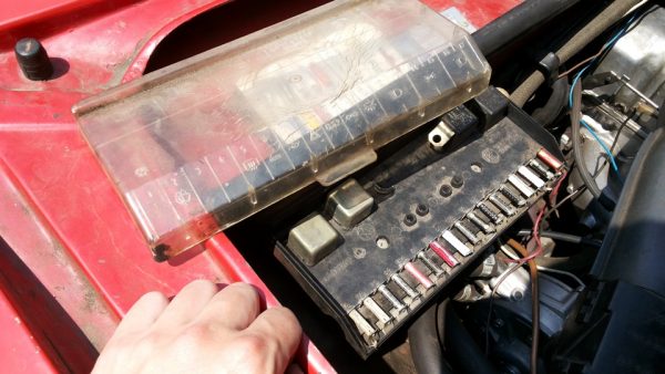
VAZ 2104 is equipped with a fuse box (BP), which is also called a mounting block, located under the hood on the passenger side. The node contains not only protective elements, but also relays responsible for switching certain devices.
How to identify a blown fuse
If there are any problems with the electrical part of the "four", you first need to look into the mounting block and check the integrity of the fuses, and only after that proceed with a more detailed troubleshooting. Structurally, the protective element may differ, depending on the PSU installed on the machine. You can check the fusible link for failure in the following ways:
- Visually;
- a multimeter.
Visual inspection
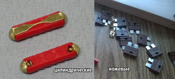
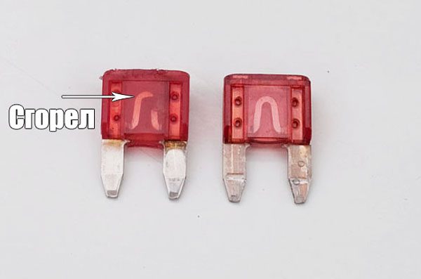
The fuses are designed in such a way that their performance can be determined by their appearance. For cylindrical elements, a special insert is located on the outside and its damage cannot be overlooked. The flag elements are equipped with a fusible insert inside, but thanks to the transparent case, its condition can be visually assessed through the light. A blown fuse will have a broken fuse.
Checking with a multimeter or control
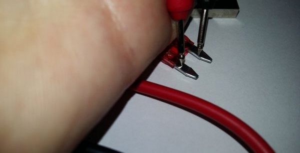
Using the device, the fuse can be checked for voltage and resistance. In the first case, the part is diagnosed directly in the mounting block. To do this, perform the following actions:
- We set the device to the voltage measurement limit.
- We turn on the circuit in the car, protected by a fusible link (stove, headlights, etc.).
- With a multimeter or control (control light), we check the voltage at one contact of the fuse, and then at the other. If there is no voltage on one of the terminals, this will mean that the fuse has blown and needs to be replaced.
Video: checking fusible links without dismantling from the machine

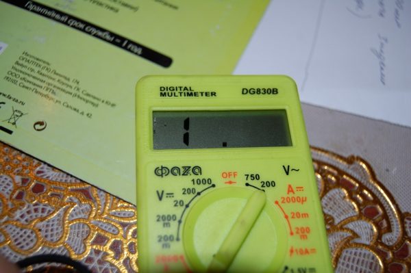
To diagnose protective elements by resistance, perform the following steps:
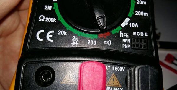
- On the multimeter, select the mode for measuring resistance or continuity.
 To check the fuse, select the appropriate limit on the device
 - We take out the checked element from the block.
- We connect the probes of the device with the contacts of the fuse.We carry out a check by touching the fuse contacts with the probes of the device
- If the part is working, then on the screen we will see zero resistance readings, indicating that the insert is working. In the event of a break, the resistance will be infinitely large, which will indicate the need to replace the element.An infinite resistance value will indicate a break in the fusible link
Some car owners, if the fuse is damaged, replace it with a coin or a piece of wire. However, such a solution to the problem is wrong and dangerous. If a short circuit occurs in the circuit, then the coin or wire will not burn out, as it would be the case with a fuse, and the wiring will begin to melt.
Old sample fuse box
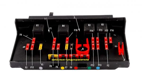
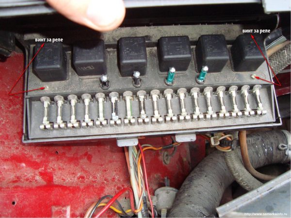
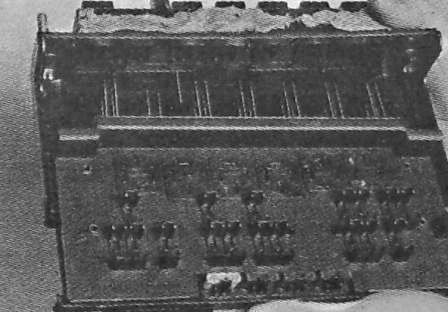
The fourth model of the Zhiguli was equipped with two types of mounting blocks - old and new. Despite some differences, both nodes perform the same function. Externally, the devices differ in a different arrangement of inserts and relays. The old version of the block was completed only a carburetor “four”, although a modified unit can also be installed on a car with a carburetor power unit. The old design provides for the installation of 17 fuses in one row and 6 relays. The inserts are held by springy contacts, which negatively affects the reliability of the block. As a result, at high currents, both the fuse and the contacts heat up, which gradually leads to their deformation and oxidation.
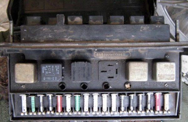
The fuse block is made on two printed circuit boards placed in the housing one above the other and connected by jumpers. Since the design is imperfect, the repair raises many questions. The main difficulties are caused by the problem of disconnecting the boards for their recovery, which is sometimes required when the tracks burn out.
The node in question is connected to the automotive wiring using colored connectors, which eliminates confusion during installation. The rear fuse box enters the passenger compartment and is located behind the glove box. The wires from the dashboard fit in the same place. The lower part of the device is located under the hood and is also equipped with multi-colored connectors for convenience.
The body of the old node itself is made of plastic, and a transparent cover is installed on top. Today, such a block is obsolete, and it will be quite difficult to find one in good condition.
Table: VAZ 2104 fuses and the circuits they protect
| Fuse number | Current strength, A | Protected circuit |
| F1 | 10 | Rear lights (reverse light) Heater motor Control lamp and rear window heating relay (winding) |
| F2 | 10 | Windshield wiper and washer pump motors Windshield wiper relay |
| F3 | 10 | Spare |
| F4 | 10 | Spare |
| F5 | 20 | Rear window heating element and heating relay (contacts) |
| F6 | 10 | Cigarette lighter Portable lamp socket |
| F7 | 20 | Horns and Horn Relays Engine cooling fan motor and motor start relay (contacts) |
| F8 | 10 | Direction Indicators Switch and relay-interrupter for direction indicators and alarms in alarm mode |
| F9 | 7.5 | Generator voltage regulator (on vehicles with G-222 generator) |
| F10 | 10 | Direction indicators in turn signal mode and corresponding indicator lamp Turn signal interrupter relay Turn signal indicator Tachometer Fuel gauge Coolant temperature gauge Voltmeter Relay for turning on the fan motor (winding) Control lamp of a charge of the rechargeable battery Control lamps of a reserve of fuel and inclusion of a parking brake Signal lamps for emergency oil pressure drop and insufficient brake fluid level A control lamp of inclusion of a parking brake Carburetor choke control lamp (for carburetor engine) Thermal switch for electric fan Carburetor air valve control system Excitation winding of the generator (generator 37.3701) |
| F11 | 10 | Rear lights (brake lights) Plafond of internal illumination of a body |
| F12 | 10 | Right headlight (high beam) Winding of the relay for switching on the headlight cleaners (when the high beam is on) |
| F13 | 10 | Left headlight (high beam) Control lamp of inclusion of a high beam of headlights |
| F14 | 10 | Left headlight (side light) Right tail light (side light) License plate lights engine compartment lamps Control lamp of inclusion of dimensional light |
| F15 | 10 | Right headlight (side light) Left rear light (side light) Cigarette lighter lamp Instrument lighting lamp Glove compartment lamp |
| F16 | 10 | Right headlight (low beam) Winding of the relay for switching on the headlight cleaners (when the dipped beam is on) |
| F17 | 10 | Left headlight (low beam) |
New sample fuse box
The latest models of "fours" with carburetor engines, as well as injection versions, were equipped with a new PSU. This product solves the problem of frequent contact loss. The use of knife fuses significantly increased the reliability of the assembly. Fusible inserts are placed in two rows, and tweezers are used to replace them, which comes with the block. There is a separate tweezer for the relay. The new version of the block is equipped with only one board, which greatly simplifies the repair.
How to remove the mounting block
The VAZ 2104 fuse box has to be removed infrequently. If such a need arises, then it is due to the repair or replacement of the unit. For dismantling, you will need the following tools:
- key on 10;
- socket head 10;
- extension.
The block is removed in the following sequence:
- Remove the negative terminal from the power supply.
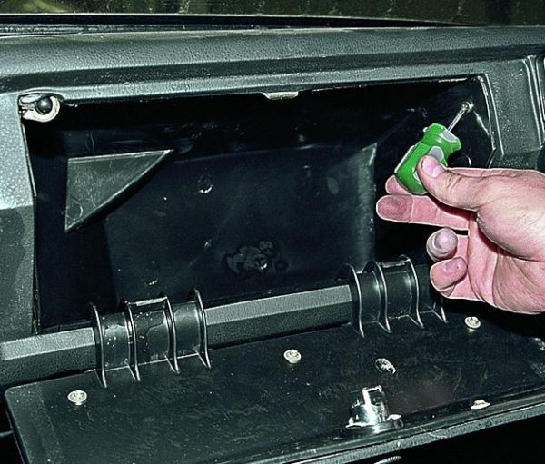
- Open the glove compartment and unscrew the fastening on the side walls, after which we remove the case from the front panel.Using a Phillips screwdriver, unscrew the glove box mount and remove the body from the torpedo
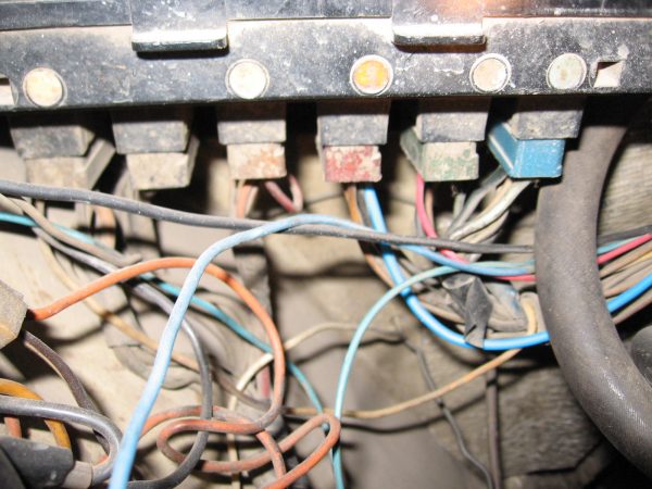
- We tighten the pads from the PSU under the hood.In the engine compartment, connectors with wires to the mounting block fit from below
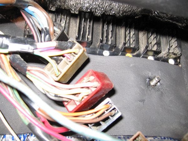
- In the cabin, we also remove the chips from the device.We remove the pads with wires that are connected to the block from the passenger compartment
- We unscrew the fastening of the assembly to the body, remove the block and the rubber seal.The block is held by four nuts - unscrew them
- Having completed the necessary work, we install in the reverse order of dismantling.
Video: how to remove a PSU using the example of the VAZ "seven"

Repair of the mounting block
Since the device in question is made on a printed circuit board, its repair is carried out only after dismantling. To disassemble the case, you only need a flat screwdriver. The event consists of the following steps:
- We remove all relays and fuse-links from the block.To disassemble the mounting block, you first need to remove all relays and fuses
- The top cover is held by four screws, unscrew them.The top cover is secured with four screws.
- We pry off the fixing elements with a screwdriver.On the side of the connectors, the case is held by latches
- Move part of the body to the side.After disconnecting the latches, we shift the block body
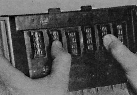
- We press our fingers on the contacts of the block.To remove the board, you must press the connectors
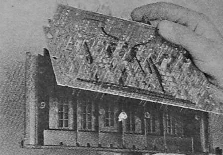
- Remove the board from the case.We remove the board by removing it from the case
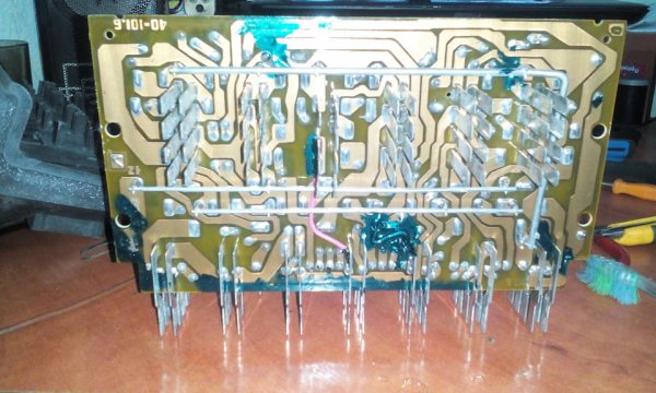
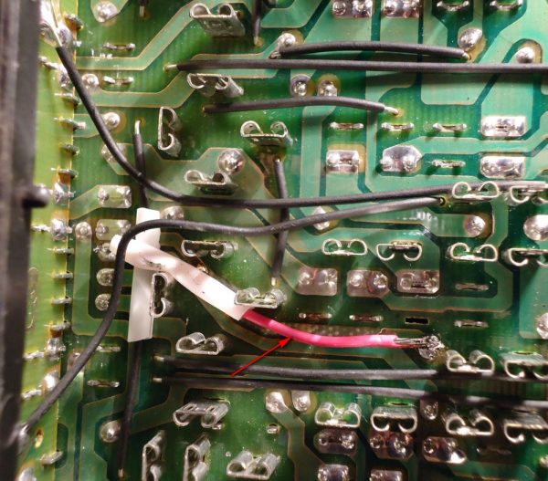
- We carefully check the condition of the board for any damage (poor soldering of contacts, integrity of the tracks). If problem areas are found on the board, we fix the breakdown. In case of significant damage that cannot be repaired, we change the part to a serviceable one.We examine the board for damage to the tracks
How to replace a burnt track
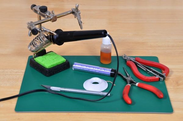
The VAZ 2104 mounting block is characterized by such a malfunction as a track burnout on the board. If this happens, then it is not necessary to replace the board, since the track can be restored. For repairs, you need to prepare the following list:
- soldering iron 40–60 W;
- solder;
- piece of wire;
- knife.
The repair sequence may vary depending on the damage, but in general it is carried out as follows:
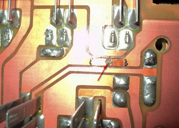
- We clean the damaged track until the varnish at the break is completely removed.The damaged section of the track must be cleaned with a knife
- We bring a soldering iron with a drop of solder and connect the broken track.Having tinned the track, we restore it with a drop of solder
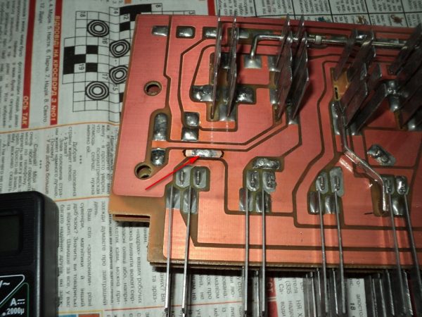
- In case of severe damage to the conductive track, for restoration we use a piece of wire, through which we connect the contacts together.In case of significant damage to the track, it is restored with a piece of wire
- At the end of the repair, we mount the board in the case and put the unit in place.
Video: repair of the Zhiguli mounting block

How to test a relay
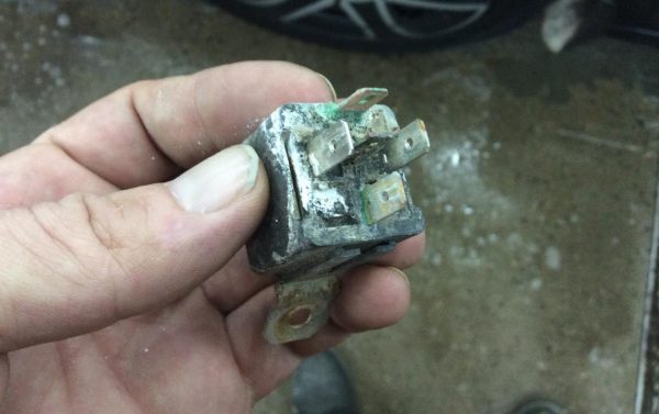
With the relay in the mounting block of the "four" sometimes there are problems. Often the problem is caused by poor contact in the connectors, which can be identified by the color of the relay outputs: a white or green coating indicates oxidation and the need for cleaning. For these purposes, fine sandpaper is used. You can check the relay by replacing it with a known-good element or by supplying power to the winding contacts. If the operation of the switching element is restored after replacement, then the old part is out of order.
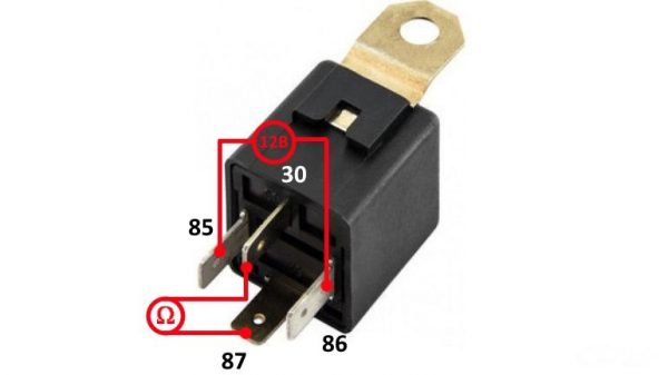
In the second case, the relay coil is energized from the battery, and the closing and opening of the contacts is checked with a multimeter. The presence of resistance when closing the contacts will indicate a malfunction of the switching element and the need to replace it.
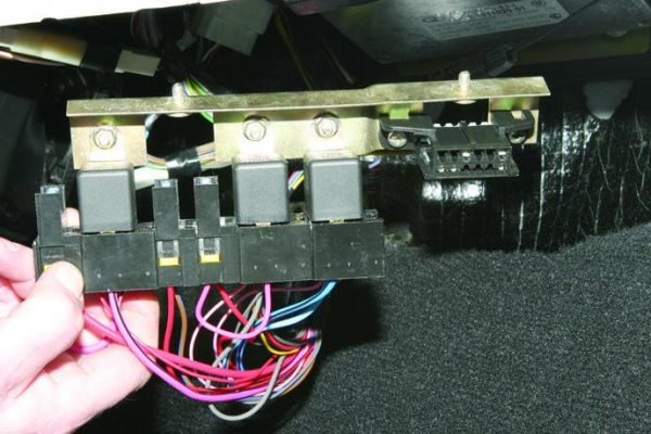
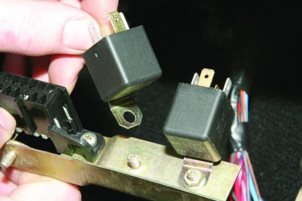
Fuse box in the cabin of the "four"
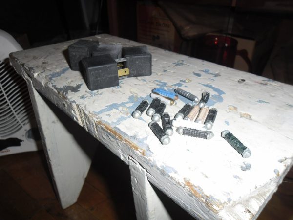
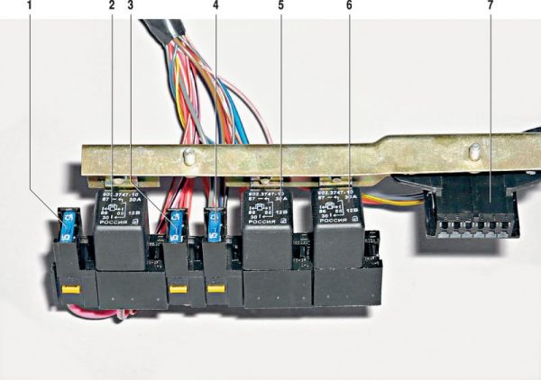
Most modifications of the VAZ 2104 are equipped with only one PSU - in the engine compartment. However, injection versions of this car have an additional unit, which is located in the cabin under the glove box. This block is a bar with several elements located on it:
- main relay;
- fuel pump relay;
- fan relay.
Fused links provide protection for:
- main relay;
- electric fuel pump;
- electronic engine control unit.
How to remove the fuse box
The need to remove the PSU may arise when replacing the relay or protective elements of the motor control system. To do this, the bar itself is dismantled, on which the parts are held. The procedure is as follows:
- We de-energize the on-board network by removing the terminal from the battery minus.
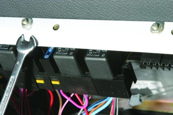
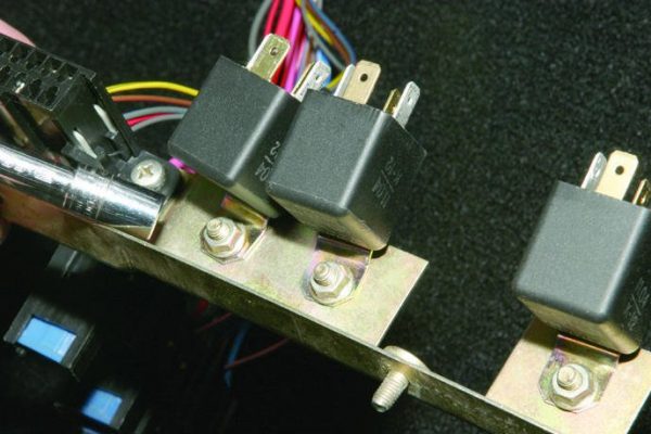
- We unscrew the fasteners of the bracket to the body.The bracket is fastened with two wrench nuts for 8
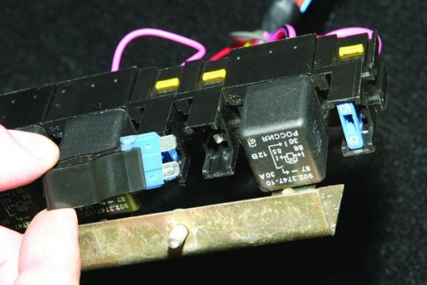
- We remove the bar with the elements.Having unscrewed the nuts, remove the bracket along with the relay, fuses and diagnostic connector
- Using special tongs, we take out the damaged fuse and replace it with a new one, taking into account the rating.To remove the fuse, you will need special tweezers
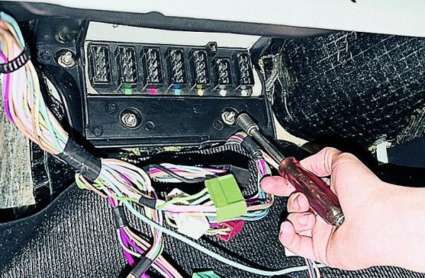
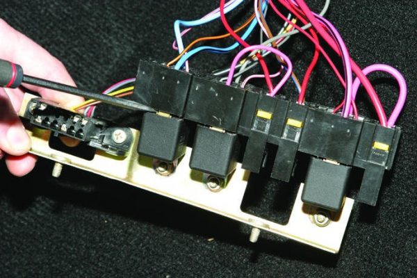
- If you need to replace the relay, then use a negative screwdriver to disconnect the connector and the switching element.To remove the connectors from the relay unit, we pry them with a flat screwdriver
- We unscrew the mount and remove the relay.The relay is attached to the bracket with a wrench nut for 8
- We change the part and assemble in the reverse order.After removing the failed relay, install a new one in its place.
The connection of the elements in the additional block VAZ 2104 is made on the connectors and in the event of a malfunction, only the details change.
To improve the reliability of the electrical equipment of the VAZ "four", it is advisable to install a new model of the fuse box. If this is not possible, then periodic repairs of the old block can be performed with a minimum set of tools and without special knowledge. It will be enough to familiarize yourself with the step-by-step instructions and follow it during the repair process.

