Motorcycle instrument assembly
Content
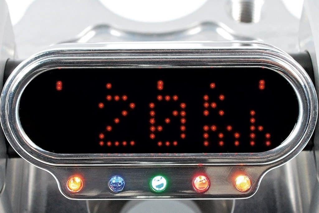
Small and thin tools are needed on custom motorcycles. The conversion can be done even by amateur craftsmen. We'll show you how to do this using the motorcycle gadget tools as an example.
Preparing for conversion
Small, intricate and precise: custom motorcycle gadget tools are a real feast for the eyes. For many bikers, circuit diagrams and other electronic systems are not popular topics. Current and voltage remain invisible, except when the cables are attacked and cause sparks. However, installing instruments in the cockpit of models of roadsters, choppers or fighters is not so difficult.
Prior knowledge
Basic electrical terms such as current, voltage, and positive and negative terminals should be familiar to anyone who wants to work with their motorcycle's electrical circuits. As far as possible, you should have an electrical diagram and understand it at least in general terms: you should be able to identify and trace the cables of various components, such as, for example. battery, ignition coil, steering lock, etc.
Attention: Before starting any connection work, the battery must always be completely disconnected from the on-board network. We recommend that you additionally use a flying rocket (included in the kit) with the device.
Inductive sensors or proximity sensors at the transmission output
These sensors are most commonly used by car manufacturers. These are sensors with 3 connecting cables (supply voltage +5 V or +12 V, minus, signal), the signal of which is in most cases compatible with the devices of motorcycle gadgets. The resistor that was previously used on the sensor is no longer necessary.
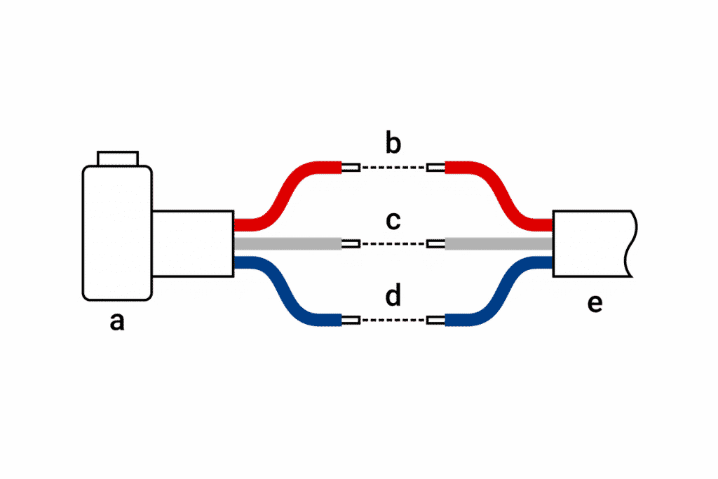
a = original speed sensor
b = + 12V
c = Signal
d = Mass / Minus
e = to the vehicle electrical system and devices
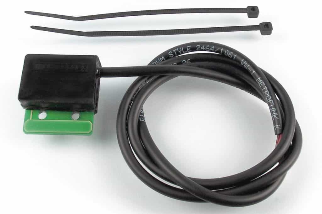
Contact Reed with a magnet on the wheel
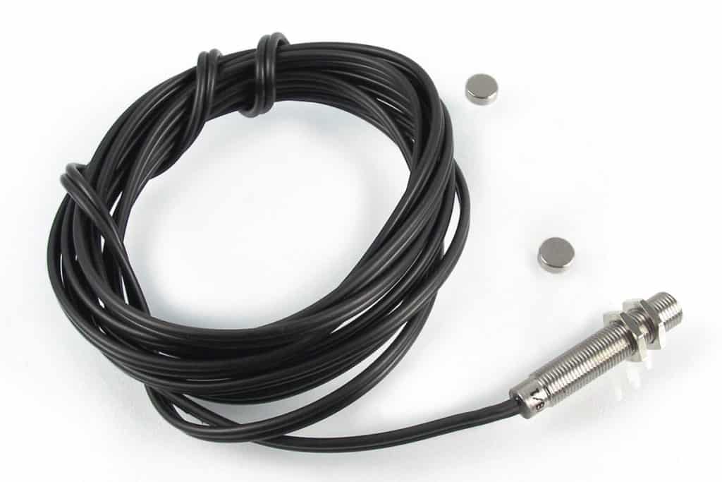
This principle is eg. famous electronic speedometers for bicycles. The sensor always responds to one or more magnets that are somewhere on the wheel. These are sensors with 2 connecting cables. To use them with your motorcycle gadgets, you must connect one of the cables to the ground/negative terminal and the other to the speedometer input.
Speed sensors retrofitted or additionally
on older cars, the speedometer still works mechanically through the shaft. In this case or when the original speed sensor is incompatible, it is necessary to use the sensor supplied with the device of the motorcycle gadget (this is a reed contact with a magnet). You can install the sensor on the fork (then install the magnet on the front wheel), on the swingarm or on the brake caliper support (then install the magnet on the rear wheel / chainring). The most suitable point from a mechanical point of view depends on the vehicle. You may need to bend and secure the small sensor support plate. You should choose a sufficiently stable binding. You can glue the magnets to the wheel hub, brake disc holder, sprocket or any other similar part with two-part adhesive. The closer the magnet is to the wheel axis, the less centrifugal force acts on it. Of course, it must be exactly aligned with the end of the sensor, and the distance from the magnet to the sensor should not exceed 4 mm.
Tachometer
Typically, an ignition pulse is used to measure and display engine speed. It should be compatible with the tool. Basically, there are two types of ignition or ignition signals:
Ignition with negative input pulse
These are ignition contacts with mechanical ignition contacts (classic and old models), electronic analog ignition and electronic digital ignition. The latter two are also referred to as solid state ignition / battery ignition. All electronic engine control units (ECUs) with combined injection / ignition are equipped with semiconductor ignition systems. With this type of ignition, you can connect the devices of the motorcycle gadget directly to the primary circuit of the ignition coil (terminal 1, terminal minus). If the vehicle has an electronic tachometer as standard, or if the ignition / engine management system has its own tachometer output, you can also use that to connect. The only exceptions are cars in which the ignition coils are built into the spark plug terminals and in which the original devices are simultaneously controlled via the CAN bus. For these vehicles, getting the ignition signal can be a problem.
Ignition with positive pulse input
This is only ignition from the discharge of the capacitor. These ignitions are also called CDI (capacitor discharge ignition) or high voltage ignition. These “self-generator” ignitions do not require, for example. without a battery to operate and are often used on enduro, single cylinder and subcompact motorcycles. If you have this type of ignition, you must use an ignition signal receiver.
The note : Japanese motorcycle manufacturers refer to electronic ignition systems as described in a) for road bikes, also partly by the abbreviation "CDI". This often leads to misunderstandings!
The difference between different types of ignition
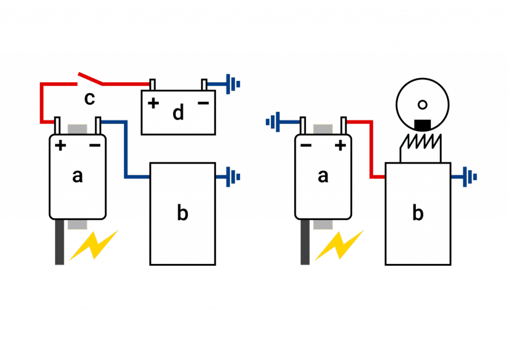
In general, it can be said that road cars with multi-cylinder engines are in most cases equipped with transistor ignitions, while single-cylinder motorcycles (even with large displacement) and small displacement are often equipped. . You can see this relatively easily by connecting the ignition coils. In the case of transistorized ignition, one of the terminals of the ignition coil is connected to the positive after contact with the on-board power supply, and the other to the ignition unit (negative terminal). In case of ignition from a capacitor discharge, one of the terminals is directly connected to the ground / negative terminal, and the other to the ignition unit (positive terminal).
Menu Button
Motogadget devices are universal, so they need to be calibrated and adjusted on the car. You can also view or reset various measured values on the screen. These operations are performed using a small button supplied with the motorcycle gadget device. If you do not want to install an additional button, you can also use the warning light button if it is connected to the negative terminal (de-energized).
a = Ignition coil
b = Ignition / ECU
c = Steering lock
d = Battery
Wiring diagram - Example: motoscope mini
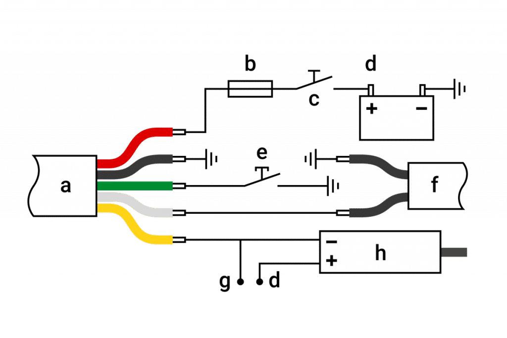
a = Tool
b = Fuse
c = Steering lock
d = + 12V
e = Press button
f = Contact Reed
g = From ignition / ECU
h = Ignition coil
Commissioning
After the sensors and the instrument are mechanically stable and all connections are correctly connected, you can reconnect the battery and use the instrument. Then enter vehicle-specific values in the setup menu and calibrate the speedometer. Detailed information on this can be found in the operating instructions for the respective device.