Coupling devices of tractors
The kinematic and force interaction of the transport links of the road train with the trailer is carried out by means of a towing device (Fig. 1).
Traction coupling devices (TSU) of the tractor consist of a removable coupling mechanism, a damping element and fixing parts.
According to the design of the detachable coupling mechanism, towing devices are divided into:
- crochet (pair of hooks and loops),
- pins (pair of pins-loops),
- ball (ball-loop pair).
The damping element uses coil springs, rubber elements and ring springs.
The most widespread on road trains with trailers are hook-and-joint hitches.
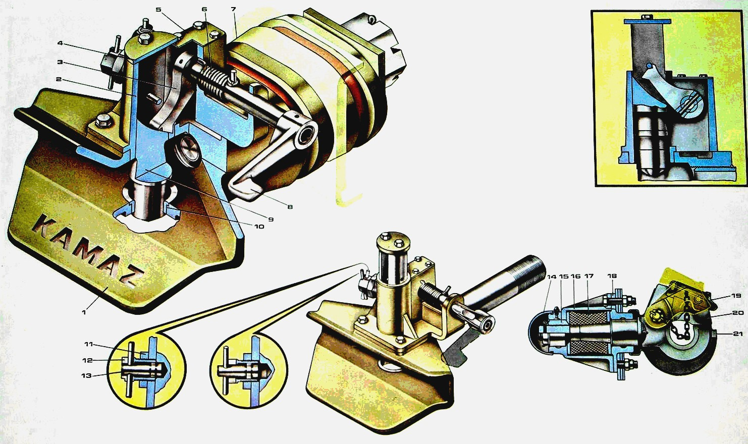
Figure 1 - Tractor coupling devices: 1 - receiver; 2 - body of the actuator; 3 – fixing lever; 4 - kingpin cover; 5 - mechanism housing cover; 6 - spring; 7 - frame; 8 – drive handle; 9 - central pin; 10 - saddle of the central kingpin; 11 - locknut; 12 - fuse box; 13 — fuse automatic decoupling; 14 – a cap of a nut of a hook of the end mechanism; 15 - nut; 16 - body of the towing device; 17– stopper of the towing device; 18 - cover of the towing device; 19 - ratchet lock hook; 20 - latch; 21 - hook
The hook hitch of the KamAZ-5320 vehicle (Fig. 2) consists of a hook 2, the rod of which passes through the holes in the rear cross member of the frame, which has additional reinforcement. The rod is inserted into a massive cylindrical body 15, closed on one side by a protective cap 12, on the other side by a casing 16. A rubber elastic element (shock absorber) 9, which softens shock loads when starting a car from a place with a trailer from a place and when driving on an uneven road, it is located between two washers 13 and 14. The nut 10 provides a preliminary compression of the rubber stop 9. On the shaft 3 passing through the hook, blocked by the pawl 4, which prevents the coupling loop from disengaging from the hook.
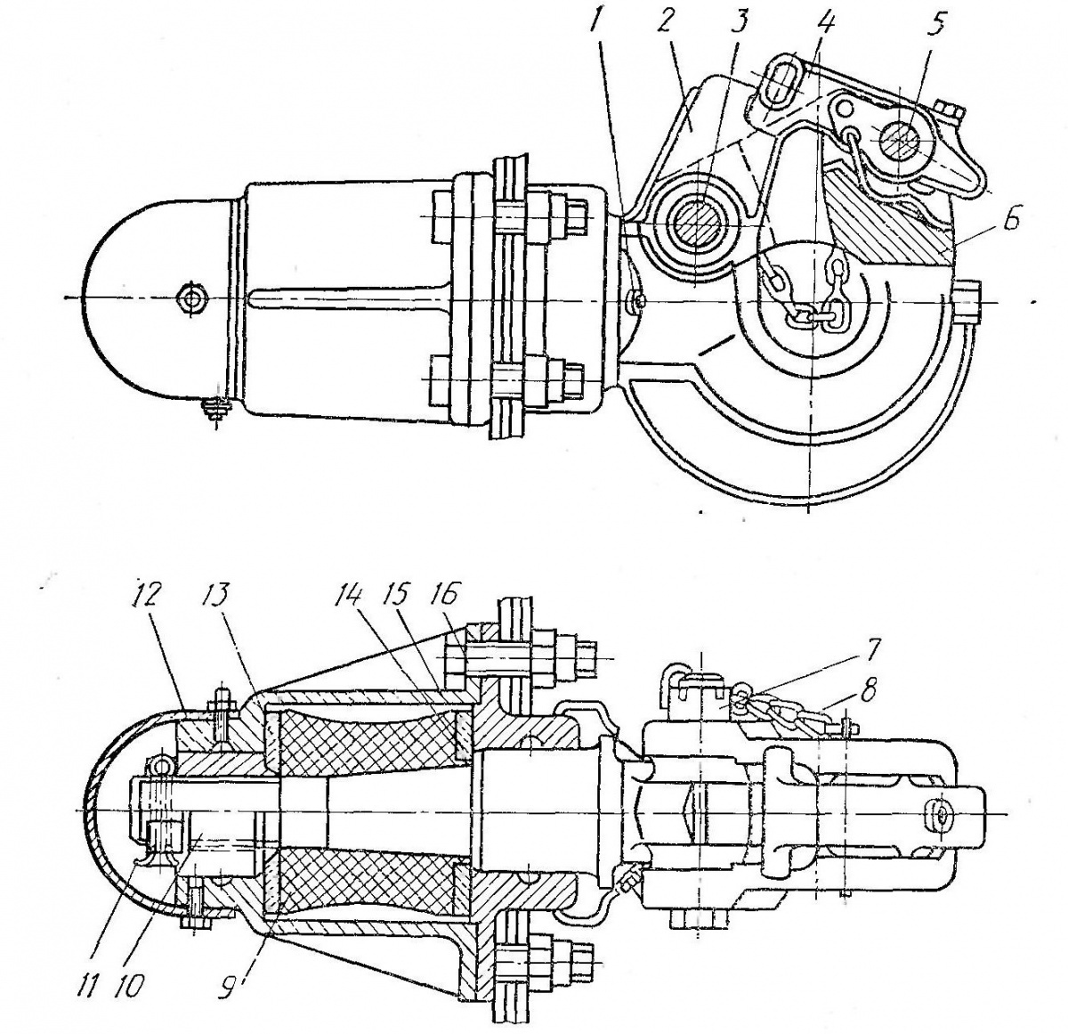
Figure 2 - Towing hook: 1 - oiler; 2 - hook; 3 - the axis of the latch hook; 4 - pawl latch; 5 - ratchet axis; 6 - latch; 7 - nut; 8 - a chain of cotter pins; 9 - elastic element; 10 - hook-nut; 11 - cotter pin; 12 - protective cover; 13, 14 - washers; 15 - body; 16 - housing cover
To hitch a tractor with a trailer:
- brake the trailer with the parking brake system;
- open the latch of the tow hook;
- install the trailer drawbar so that the hitch eye is on the same level as the vehicle's towing hook;
- carefully lift the car back until the towing hook rests on the trailer hitch;
- put the towing loop on the towing hook, close the latch and fix it with a ratchet;
- plug the trailer into the vehicle socket;
- connect the hose fittings of the pneumatic system of the trailer with the corresponding fittings of the pneumatic system of the car;
- connect the trailer to the car with a safety cable or chain;
- open the valves for shutting off the pneumatic drive of the trailer brake systems installed on the vehicle (single-wire or two-wire circuit);
- brake the trailer with the parking brake system.
The articulated hitch differs from the hook design of the detachable hitch mechanism.
The detachable-coupling mechanism of the pivot hinge (Fig. 3) consists of a fork 17 (“receiver”), a pivot 14 and a bolt. The curtain placed on the body consists of a handle 13, a shaft, a belt 12 and a load spring 16. The fork is connected to the rod 5 through the shaft 10, which provides the necessary flexibility of the transmission in the vertical plane. In the free state, the detachable coupling mechanism is held by a rubber stop 11 and a spring bar 9.
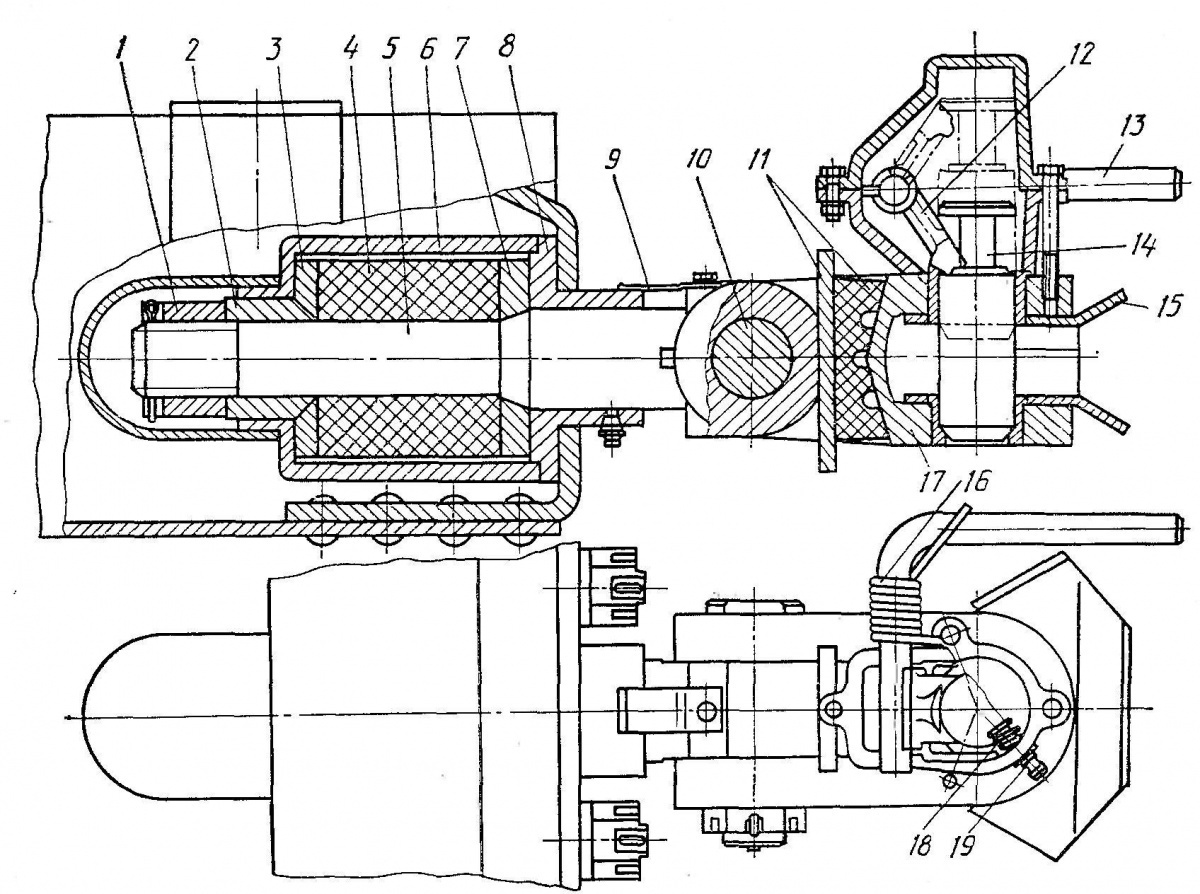
Figure 3 - Rotating drawbar: 1 - nut; 2 - guide sleeve; 3, 7 - flanges; 4 - rubber element; 5 - rod; 6 - body; 8 - cover; 9 - spring; 10 – rod axis; 11 - buffer; 12 - bar; 13 - handle 14 - kingpin; 15 - guide loop; 16, 18 - springs; 17 - fork; 19 - fuse
Before coupling the tractor with the trailer, the latch is “cocked” with the handle 13, while the pin 14 is held by the clamp 12 in the upper position. Spring 16 is compressed. The lower conical end of the kingpin 14 partially protrudes from the upper strut 17 of the fork. The trailer hitch loop enters the fork guide 15 when the curtain is lowered. The strap 12 releases the central hinge 14, which, under the action of gravity and the spring 16, moves downward, forming a hook. The fall of the kingpin 14 from the reciprocal hole is prevented by the fuse 19. When engaged, the reciprocal loop enters the fork of the TSU and presses the cone-shaped bottom of the kingpin 14, which helps to raise it a short distance and release the pawl (yoke) 12 from the kingpin.
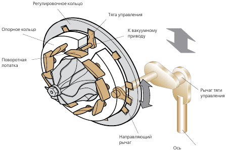
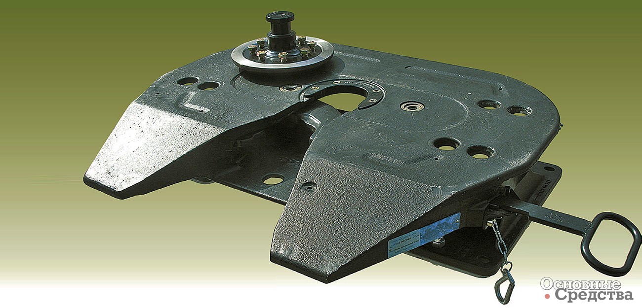
The power and kinematic interaction of the transport links of the saddle road train is provided by a fifth wheel coupling (Fig. 4).
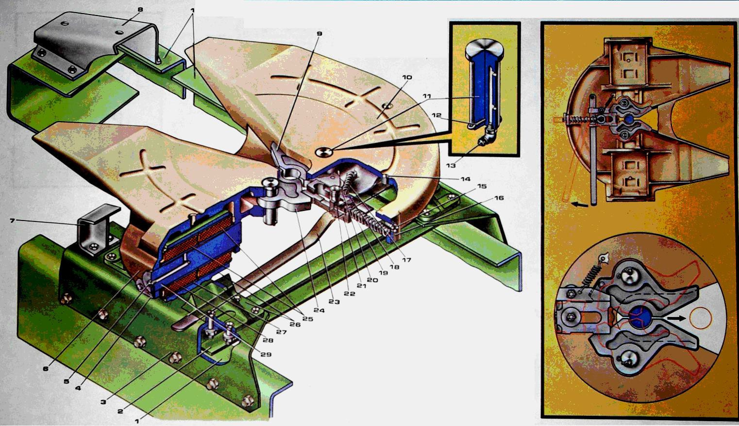
Figure 4 - Truck tractor: 1 - vehicle chassis; 2 - cross member of the saddle device; 3 - saddle support; 4 - butt plate; 5 - oiler; 6 - side eyes of the saddle; 7 - saddle bracket; 8 - saddle sliding device; 9 - left sponge; 10 - bearing surface of the base plate; 11 - spongy finger; 12 - cotter pin; 13 - oiler; 14 - pin for attaching the handle; 15 - axis of the safety bar; 16 - fuse for automatic disengagement of the coupling mechanism; 17 - spring ratchet locking cuff; 18 - axis of the locking fist pawl; 19 - locking cam spring; 20 - dog's clenched fist; 21 - locking fist; 22 - axis of the locking fist; 23 - handle of the handle lock; 24 - sponge right; 25 - hinge; 26 - support; 27 - outer sleeve; 28 - inner sleeve; 29 - hinge axis
The fifth wheel coupling is used to connect and disconnect the tractor from the semi-trailer, as well as to transfer a significant vertical load from the semi-trailer to the vehicle and traction from the tractor to the semi-trailer.
The device provides semi-automatic coupling and uncoupling of a tractor with a semi-trailer. The trailer is equipped with a base plate with a pivot (Fig. 5). The diameter of the working surface of the king pin is normalized and equal to 50,8 ± 0,1 mm.

Figure 5 - Semi-trailer kingpin for coupling with tractor fifth wheel coupling
The fifth wheel coupling (Fig. 4) is mounted on the frame of the truck tractor using two brackets 3 connected by a cross member 2. The brackets 3 have lugs on which the saddle is installed using two hinges 25, which is a base plate 10 with two side protrusions 6.
The side eyes 6 of the saddle are rigidly connected to the axes 29 of the hinges 25, which provide a certain inclination of the saddle in the longitudinal plane. Axles 29 rotate freely in rubber-metal bushings 27 and 28. This solution provides a certain longitudinal inclination of the semi-trailer during movement, as well as a slight transverse inclination (up to 3º), which means it reduces the dynamic loads transmitted by the trailer semi-trailer to the tractor frame. Shafts 29 are protected from axial movement by locking plates 4. Oiler 5 is installed on the shaft and a channel is made for supplying lubricant to rubber and metal bushings 27.
Under the base plate 10 of the seat there is a coupling mechanism. It consists of two handles 9 and 24 (“sponges”), a locking handle 21 with a stem and a spring 19, a latch with a spring 17, an opening control lever 23 and an automatic decoupling fuse 16 fixed on the base plate 10 using pins 11 and can be rotate around them, taking two extreme positions (open or closed). The lock handle 21 also has two extreme positions: rear - handles are closed, front - handles are open. The spring 19 of the rod counteracts the movement of the handle 21 to the forward position. The locking fist rod 21 abuts against the self-exploding bar 16. Thus.
The fusible rod 16 is mounted on the axis 15 with the possibility of its rotation to fix or loosen the rod.
Before connecting the tractor to the trailer, the automatic release safety bar is set to the “unlocked” position, which releases the handle striker bar.
To hitch the tractor with the semi-trailer, turn the hitch control lever forward in the direction of travel of the vehicle. In this case, the locking handle will be locked in the frontmost position with a latch. The driver sets the tractor in such a way that the semi-trailer kingpin passes between the beveled ends of the seat and further between the handles. Since the handle is latched in the cocked position, when the king pin is inserted into the groove of the handles, the handles open.
The fist is released from fixation by a latch, rests with its back against the grips and holds them in the open state. With further movement of the rear part of the tractor, the kingpin acts on the handles in such a way that they close, and the handle, under the action of a spring, enters the angular grooves of the handles and occupies the rearmost position, which ensures its reliable lock. After locking has occurred, it is necessary to fix the first rod by turning the self-opening fuse bar to the “locked” position.
To start moving with a semi-trailer, the driver must: raise the rollers (or cylinders) of the semi-trailer supporting device; connect the heads of the pneumatic systems of the tractor and the semi-trailer; connect electrical wires; disengage trailer parking brake
Before uncoupling the road train, the driver brakes the semi-trailer with the parking brake system, lowers the rollers (or cylinders) of the supporting device, disconnects the connecting heads of the pneumatic system and the plugs of the electrical cables.
To disengage, turn the fuse bar and the disengagement control lever again, then move the tractor smoothly forward in first gear. Since the trunnion will be moved to the forward position and locked with a latch, the trailer kingpin will freely pop out of the folding handles.
To increase the carrying capacity of a road train, shortened telescopic coupling devices are used, the principle of operation of which is based on reducing the distance between the tractor and trailer during rectilinear movement and increasing it when cornering and maneuvering.
The increase in the carrying capacity of road trains is associated with an increase in the number of axles and their total length. However, this causes a deterioration in the maneuverability of the road train and accelerated tire wear.
The use of wheel axles and wheel axles reduces these drawbacks. They are simple in design and require low production and maintenance costs.
In two- and three-axle semi-trailers, the rear axle rotates under the action of the lateral components of the reactions of the road to its wheels when turning.
Articulated axles increase the loading height and center of gravity of the semi-trailer. Therefore, axles with self-aligning wheels have become widespread.