Car generator circuit
Content
The most basic generator function - battery charge battery and power supply of electrical equipment of the internal combustion engine.
Therefore, let's take a closer look generator circuithow to connect it correctly, and also give some tips on how to check it yourself.
Generator A mechanism that converts mechanical energy into electrical energy. The generator has a shaft on which a pulley is mounted, through which it receives rotation from the ICE crankshaft.
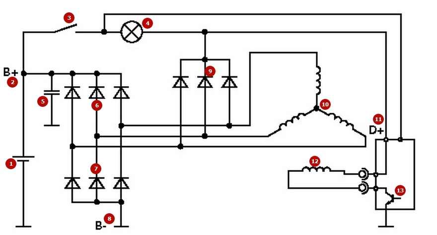
- Accumulator battery
- Generator output “+”
- Ignition switch
- Alternator health indicator lamp
- Noise suppression capacitor
- Positive Power Rectifier Diodes
- Negative Power Rectifier Diodes
- "Mass" of the generator
- Excitation diodes
- Windings of three phases of the stator
- Field winding supply, reference voltage for voltage regulator
- Excitation winding (rotor)
- Voltage regulator
a machine generator is used to power electrical consumers, such as: an ignition system, an on-board computer, machine lighting, a diagnostic system, and it is also possible to charge a machine battery. The power of a passenger car generator is approximately 1 kW. machine generators are quite reliable in operation, because they ensure the uninterrupted operation of many devices in the car, and therefore the requirements for them are appropriate.
Generator device
The device of a machine generator implies the presence of its own rectifier and control circuit. The generating part of the generator, using a fixed winding (stator), generates a three-phase alternating current, which is further rectified by a series of six large diodes and the direct current charges the battery. Alternating current is induced by the rotating magnetic field of the winding (around the field winding or rotor). then the current through the brushes and slip rings is fed to the electronic circuit.
Generator device: 1. Nut. 2. Washer. 3.Pulley. 4. Front cover. 5. Distance ring. 6. Rotor. 7. Stator. 8.Rear cover. 9. Casing. 10. Gasket. 11. Protective sleeve. 12. Rectifier unit with capacitor. 13. Brush holder with voltage regulator.
The generator is located in front of the internal combustion engine of the car and is started using the crankshaft. The connection diagram and the principle of operation of the car generator are the same for any car. Of course, there are some differences, but they are usually associated with the quality of the manufactured goods, the power and layout of the components in the motor. In all modern cars, alternating current generator sets are installed, which include not only the generator itself, but also a voltage regulator. The regulator equally distributes the current strength in the field winding, it is due to this that the power of the generator set itself fluctuates at the moment when the voltage at the output power terminals remains unchanged.
The principle of operation of the auto generator
Connection diagram of the generator VAZ 2110-2115
Generator connection diagram alternating current includes the following components:
- Battery.
- Generator.
- Fuse block.
- Ignition.
- Dashboard.
- Rectifier block and additional diodes.
The principle of operation is quite simple, when the ignition is turned on, plus through the ignition switch goes through the fuse box, light bulb, diode bridge and goes through the resistor to minus. When the light on the dashboard lights up, then the plus goes to the generator (to the excitation winding), then in the process of starting the internal combustion engine, the pulley begins to rotate, the armature also rotates, due to electromagnetic induction, an electromotive force is generated and alternating current appears.
further into the rectifier unit through a sinusoid to the left shoulder, the diode passes plus, and minus to the right. Additional diodes on the light bulb cut off the minuses and only pluses are obtained, then it goes to the dashboard node, and the diode that is there it passes only the minus, as a result, the light goes out and the plus then goes through the resistor and goes to minus.
The principle of operation of a machine constant generator can be explained as follows: a small direct current begins to flow through the excitation winding, which is regulated by the control unit and maintained at a level of just over 14 V. Most generators in a car are capable of producing at least 45 amperes. The generator runs at 3000 rpm and above - if you look at the ratio of the sizes of the fan belts for the pulleys, then it will be two or three to one in relation to the frequency of the internal combustion engine.
To avoid this, the plates and other parts of the generator rectifier are partially or completely covered with an insulating layer. In a monolithic design of the rectifier unit, heat sinks are mainly combined with mounting plates made of insulating material, reinforced with connecting bars.
then we will consider the connection diagram of the machine generator using the example of a VAZ-2107 car.
Wiring diagram for a generator on a VAZ 2107
The VAZ 2107 charging scheme depends on the type of generator used. in order to recharge the battery on such cars as: VAZ-2107, VAZ-2104, VAZ-2105, which are on a carburetor internal combustion engine, a G-222 type generator or its equivalent with a maximum output current of 55A will be needed. In turn, VAZ-2107 cars with an injection internal combustion engine use a generator 5142.3771 or its prototype, which is called an increased energy generator, with a maximum output current of 80-90A. you can also install more powerful generators with a return current of up to 100A. Rectifier units and voltage regulators are built into absolutely all types of alternators; they are usually made in one housing with brushes or removable and mounted on the housing itself.
The VAZ 2107 charging scheme has slight differences depending on the year of manufacture of the car. The most important difference is the presence or absence of a charge control lamp, which is located on the instrument panel, as well as the way it is connected and the presence or absence of a voltmeter. Such schemes are mainly used on carbureted cars, while the scheme does not change on cars with injection ICEs, it is identical to those cars that were previously manufactured.
Generator set designations:
- “Plus” of the power rectifier: “+”, V, 30, V+, BAT.
- “Ground”: “-”, D-, 31, B-, M, E, GRD.
- Field winding output: W, 67, DF, F, EXC, E, FLD.
- Conclusion for connection with a lamp of serviceability control: D, D+, 61, L, WL, IND.
- Phase output: ~, W, R, STA.
- Output of the zero point of the stator winding: 0, MP.
- The output of the voltage regulator for connecting it to the on-board network, usually to the “+” battery: B, 15, S.
- The output of the voltage regulator to power it from the ignition switch: IG.
- The output of the voltage regulator for connecting it to the on-board computer: FR, F.
Scheme of the generator VAZ-2107 type 37.3701
- Accumulator battery.
- Generator.
- Voltage regulator.
- Mounting block.
- The ignition switch.
- Voltmeter.
- Battery charge indicator lamp.
When the ignition is turned on, the plus from the lock goes to fuse No. 10, and then it goes to the battery charge control lamp relay, then goes to the contact and to the coil output. The second output of the coil interacts with the central output of the starter, where all three windings are connected. If the relay contacts are closed, then the control lamp is on. When the internal combustion engine is started, the generator generates current and an alternating voltage of 7V appears on the windings. A current flows through the relay coil and the armature begins to attract, while the contacts open. Generator No. 15 passes current through fuse No. 9. Similarly, the excitation winding receives power through the brush voltage generator.
VAZ charging scheme with injection ICEs
Such a scheme is identical to the schemes on other VAZ models. It differs from the previous ones in the way of excitation and control for the serviceability of the generator. It can be carried out using a special control lamp and a voltmeter on the instrument panel. Also, through the charge lamp, the initial excitation of the generator occurs at the moment of starting work. During operation, the generator operates “anonymously”, that is, excitation goes directly from the 30th output. When the ignition is turned on, power through fuse No. 10 goes to the charging lamp in the instrument panel. further through the mounting block enters the 61st output. Three additional diodes provide power to the voltage regulator, which in turn transmits it to the excitation winding of the generator. In this case, the control lamp will light up. It is at the very moment when the generator will work on the plates of the rectifier bridge that the voltage will be much higher than that of the battery. In this case, the control lamp will not burn, because the voltage on its side on the additional diodes will be lower than on the side of the stator winding and the diodes will close. If during the operation of the generator the control lamp lights up to the floor, this may mean that additional diodes are broken.
Checking generator operation
You can check the generator’s performance in several ways using certain methods, for example: you can check the return voltage of the generator, the voltage drop on the wire that connects the current output of the generator to the battery, or check the regulated voltage.
To check, you will need a multimeter, a machine battery and a lamp with soldered wires, wires for connecting between the generator and the battery, and you can also take a drill with a suitable head, as you may have to turn the rotor by the nut on the pulley.
Elementary check with a light bulb and a multimeter
Wiring diagram: output terminal (B+) and rotor (D+). The lamp must be connected between the main generator output B + and the D + contact. After that, we take the power wires and connect the “minus” to the negative terminal of the battery and to the generator ground, “plus”, respectively, to the plus of the generator and to the B + output of the generator. We fix it on a vice and connect it.
We turn on the tester in the (DC) constant voltage mode, we hook one probe to the battery to the “plus”, the second also, but to the “minus”. further, if everything is in working order, then the light should light up, the voltage in this case will be 12,4V. Then we take a drill and begin to turn the generator, respectively, the light at this moment will stop burning, and the voltage will already be 14,9V. Then we add a load, take an H4 halogen lamp and hang it on the battery terminal, it should light up. Then, in the same order, we connect the drill and the voltage on the voltmeter will already show 13,9V. In passive mode, the battery under the light bulb gives 12,2V, and when we turn the drill, then 13,9V.
Generator test circuit
Strictly not recommended:
- Check the generator for operability by short circuit, that is, “for a spark”.
- To allow, in order for the generator to work without consumers turned on, it is also undesirable to work with the battery disconnected.
- Connect terminal “30” (in some cases B+) to ground or terminal “67” (in some cases D+).
- Carry out welding work on the car body with the wires of the generator and battery connected.