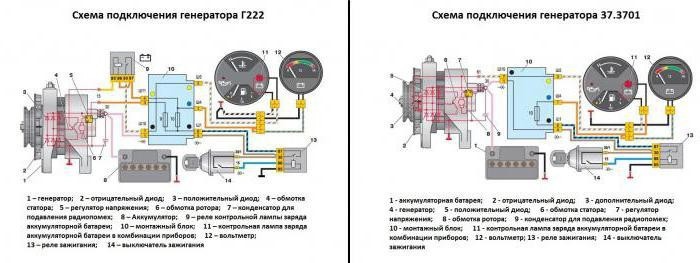
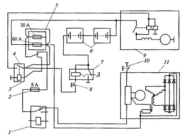
Maz generator connection diagram
Content
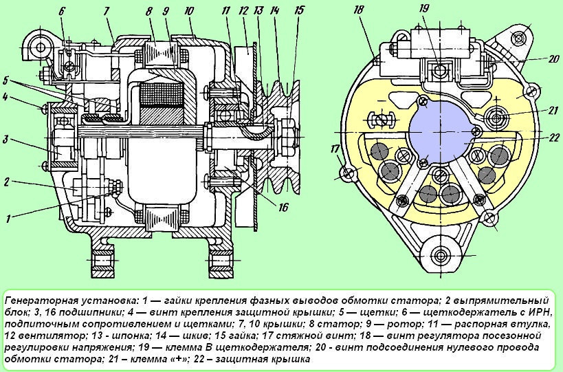
The shaft is made of steel; a steel sleeve, pole pieces and slip rings are rigidly pressed onto its corrugated surface.
Characteristics of the generating set When using it, observe the following rules: 2.
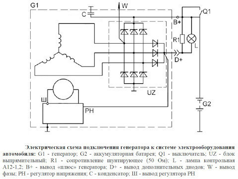
The principle of operation of the generator set G on the example of its inclusion in the electrical circuit of MAZ vehicles is shown in fig.
Correct connection of the KAMAZ Euro 2 generator. Connect the KAMAZ Euro 2 generator.
In the vehicle, the controller is deactivated. The field winding is powered by a DC source such as a battery.
The generator is cooled by continuous ventilation.
The ball bearing located on the drive side of the shaft is secured against axial displacement. If necessary, check the serviceability of indicator devices using known good ones.
Generator speed characteristic Fig. When mounting the generator on the engine, it is necessary: 2.
In the first case, it may be a cooling or fuel supply system made up of various elements.
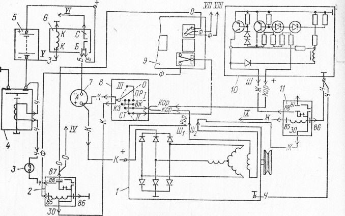
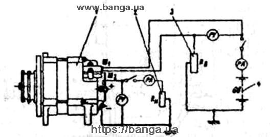
MAZ generator circuit
If the voltage increases or decreases, the regulator reduces or increases the excitation current accordingly and introduces the voltage within the required limits. The presence of permanent magnets ensures reliable self-excitation of the generator during start-up, both when powered from the battery and when it is turned off.
The presence of a constant voltage at the output can be used to signal the start of the generator, for which you can connect pilot lamps, a start blocking relay, etc.
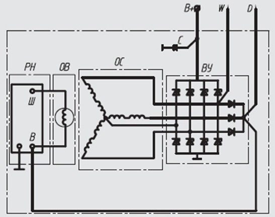
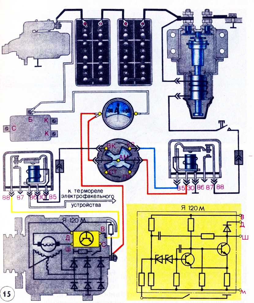
On another small-sized ceramic plate, the crystal structures of the terminal stage transistor T2, the output transistor T3 and the quenching diode D1 are located. The rectifier unit converts the alternating voltage into a constant one, and when it becomes higher than the battery voltage, the generator will start to feed the consumers and charge the battery.
When flushing the engine, it is recommended to protect the generator from water ingress. The shaft is made of steel, on its corrugated surface a steel bushing, pole pieces and contact rings are rigidly fixed by pressing.
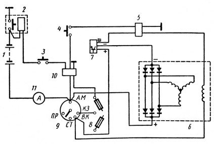
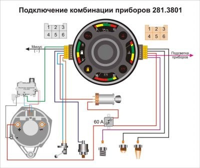
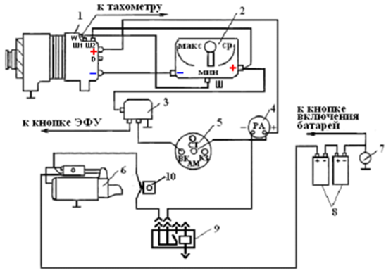
Page 1 of 3 Features of the MAZ vehicle power supply system The vehicle power supply system consists of two sources: batteries and an alternating current generator set. YaMZ generator generates current.
The side cover of the slip ring is made of aluminum alloy, has ventilation windows and a leg for attaching the generator to the engine. The higher the rotor speed and the lower the load on the generator, the higher the generator voltage.
Rotor with KS9 bearings International designation
How to connect the MAZ generator?
When flushing the engine, it is recommended to protect the generator from water ingress. Each phase consists of twelve coils connected in series, located on separate poles, for a total of 36 poles.
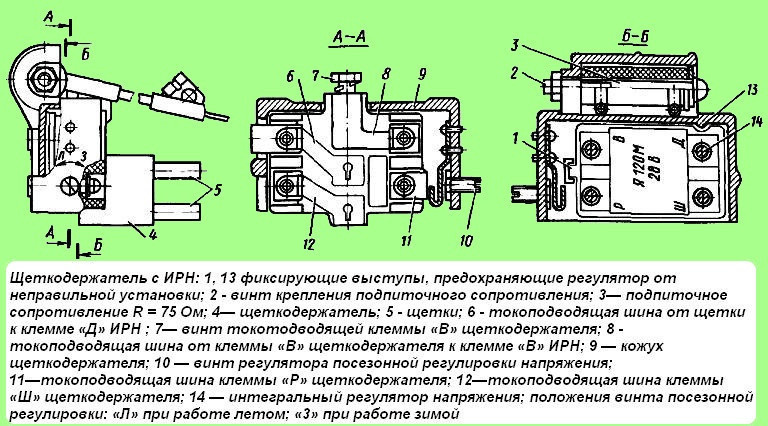
The brush holder also has a 3 x 75 ohm pull-up resistor to ensure reliable excitation of the generator set at low engine speeds. Disconnecting the battery during operation of the power unit reduces the load and leads to a malfunction of the YaMZ generator. A defective regulator and brushes must be replaced by a workshop.
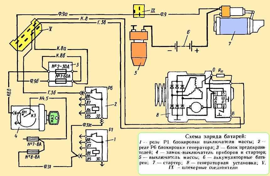
If these measures deviate from the required limits, it is necessary to determine and eliminate the network malfunction on board the vehicle. MAZ generator connection diagram Publication date: The maximum excitation current for which the structural elements of the regulator R are designed is 3,3 A.
This is done in order to discharge the contacts of the EES, since the current during the initial excitation of the generator can reach 5 A. The generator set is a twelve-pole three-phase synchronous electric machine with a built-in rectifier unit, an interference suppression capacitor, a brush holder with a voltage regulator and a ventilation system. In addition to direct functions - generating electricity to power the electrical equipment of a car, one more requirement is imposed on modern generators - it must not act or respond to radio waves.
The core is assembled from plates of electrical steel, insulated from each other with varnish and connected by welding along the outer surface of the package. And it is required for the ignition system, on-board computer, and now various devices, diagnostic and control devices, and, of course, for lighting, both signal and home.
With an increase in the rotor speed, the generator voltage can reach a dangerous value for receivers, so the generator works in conjunction with a voltage regulator that maintains the voltage in the car's on-board network within the specified limits. Since the electric motor does not operate for a short time, it ensures that the heater operates normally during the operation of the vehicle for several checks. The generator is excited by current from an independent source: batteries. During operation, check the belt tension and watch for wear on parts. The waterproofness of the generator is ensured by the use of appropriate coatings on the surface of its parts and impregnation of the windings with waterproof varnishes.
MAZ car model generators are powered by additional diodes. If the voltage increases or decreases, the regulator reduces or increases the excitation current accordingly and introduces the voltage within the required limits. Rotor 17 is a shaft with a pressed laminated package and a hub. It is impossible to check the condition of the electrical circuit and individual wires with a megohmmeter or a lamp, which is supplied with voltage above 26 V, when the generator is not turned off. After assembly, the circuit is closed with a plug and filled with a special sealant.
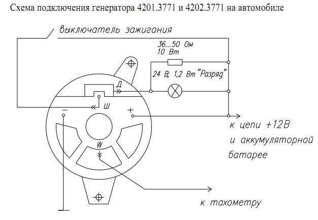
On another small-sized ceramic plate, the crystal structures of the terminal stage transistor T2, the output transistor T3 and the quenching diode D1 are located. Incorrect connection of wires and terminals leads to failure of the rectifier diodes. When checking the generator in a car, it is necessary to reconnect the cables and connect the test devices with the ground switch turned off. The output is intended for connection of a tachometer and other devices of the starter blocking relay, ABS, etc., critical to the shape of the phase signal. Generator armature stator winding phases
Scheme of connecting a backup generator to the house. Reversing switch wiring diagram.
The best prices
When checking the generator in a car, it is necessary to reconnect the cables and connect the test devices with the ground switch turned off.
The zener diode does not pass current through itself at a voltage below the stabilization voltage and breaks through, that is, as long as this state of affairs persists, the need for a car generator does not disappear - too many car elements depend on the electricity that this device generates.
Type 51 voltage regulator. This is done in order to discharge the VIP contacts, since the current during the initial excitation of the generator can reach 5 A.
Thus, the presence of a lock prevents breakage of the EFU candles of the electric torch device. With an increase in the rotor speed, the generator voltage can reach a dangerous value for receivers. Therefore, make sure that water does not get inside the part. If necessary, clean the wire connections and tighten the contact parts of the generator and the relay-regulator.
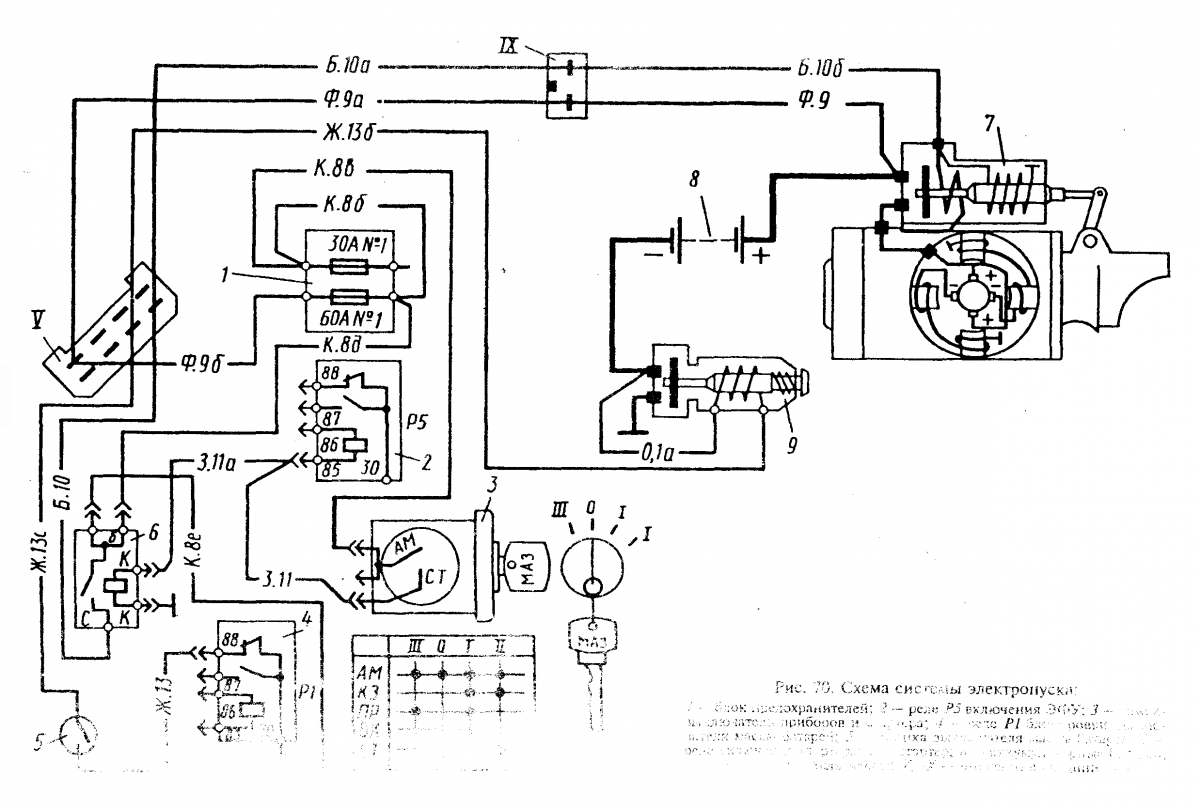
MAZ auto power supply system
The alternator case is the negative terminal and is connected to machine ground. A correctly tensioned alternator drive belt with a force of 3 kg applied to the middle of the belt branch should have a deflection of 10-15 mm.
The excitation winding of the generator is connected to the on-board network, and then the generator operates as described above, see. The ends of the excitation winding are welded to slip rings located on the insulating sleeve. Failure to comply with this requirement will eventually lead to breakdowns that will entail repair of the part. The G generator set replaces the G and G generators with their respective voltage regulators. The generator is excited by current from an independent source: batteries.
The regulator is an electronic device, closed with a lid and filled with a special sealant. Disassembly is carried out in the following order: 1. Repair of the MAZ generator, unscrew the two screws securing the brush holder by 3 cm. However, today we want to consider the device connection diagram and give some tips on operation. If necessary, we can send the purchase to any region, we work with cash and non-cash payment methods, we organize delays.
This is done in order to discharge the contacts of the EES, since the current during the initial excitation of the generator can reach 5 A. When the excitation current decreases, the generator voltage drops, the zener diodes D2 and DZ are blocked again, the circuit returns to its original position, and the generator voltage begins to grow again. Check the installation after 50 starts and at every ITV
Purpose of work and generator device