Skoda fabia 2 fuses and relays
The second generation Skoda Fabia (Mk2) was produced in 2007, 2008, 2009, 2010, 2011, 2012, 2013 and 2014 with hatchback and station wagon bodies (Fabia Combi). This model was produced with petrol and diesel engines of 1,2, 1,4, 1,6 and 1,9 liters. In this material you will find a description of the fuses and relays of the 2nd generation Skoda Fabia with diagrams and photographs of the block in which they are located.
Wrong model? Description for Fabia 1st generation read here, and for 3rd generation read here.
Blocks in the salon
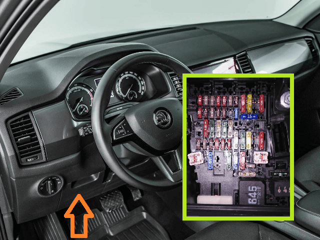
Fuse box
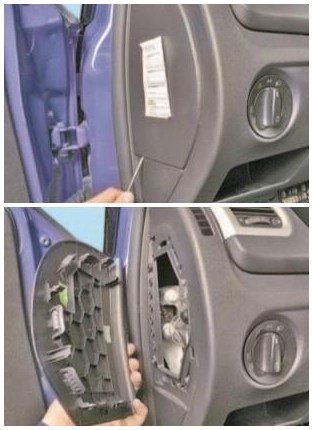
It is located under the steering wheel and is covered with a protective cover.
photo — example

The back cover should have an updated unit description for your vehicle.
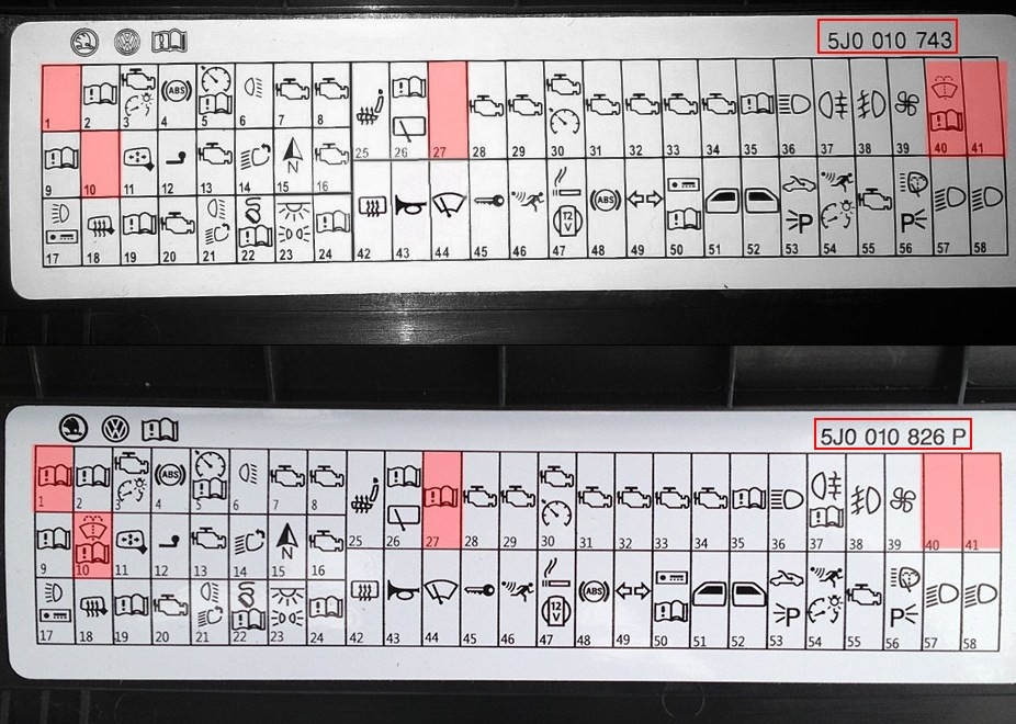
The serial number of this designation will be placed in the right corner. Here are the 4 most common options:
- 5J0010623A — Fabia 2 with 2007 to 2010 c)
- 5J0010743 — Fabia from 2010 to 2012
- 5J0010826P - Fabia from 2012 to 2015
- 5J0010675 - Fabia from 2007 to 2010.
Accordingly, the designation may also change.
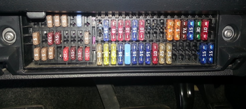
Overall plan
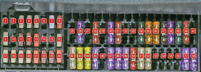
Description
- Not busy
- 5A Starter enable relay
- 7.5A Engine electronics, onboard power supply control unit, headlight range control, data bus interface diagnostics, voltage stabilizer
- 5A ABS control unit, Steering angle sensor, Start-stop mode button
- 5A Tempomat device (for gasoline engines)
- 10A Reversing lamp, (for vehicles with manual transmission)
- 5A Engine control unit, ignition system (for vehicles with manual transmission), 7.5A Engine electronics, automatic transmission selector lever
- 5A Brake pedal switch, clutch pedal switch, radiator fan control module
- 5A Control unit for adaptive lighting and headlight range control, Control unit for air conditioning, climate control, radiator fan, parking sensors control unit.
- not busy
- 5A Exterior mirror adjustment
- 5A Trailer detection control unit
- 5A Dual clutch transmission mechatronics, automatic transmission control unit
- 10A Left adaptive headlight module, right adaptive headlight module
- Voltage converter 5A 12V/5V, Navigation
- 5A Engine control unit, fuel pump relay, speedometer sensor (for vehicles without ABS), fuel pump control unit
- 7,5 A Left or right daytime running light (DRL), left or right LED DRL and parking light module
- 5A Heated exterior mirrors
- 5A Contact S
- 15A Fuel pump control unit
- 10A Reversing lamp for vehicles with automatic transmission or fog lamps when connected via BCM
- 7,5A Dashboard, diagnostic connector, air conditioning control unit, multifunction steering wheel (without start-stop system)
- 15A Interior body lighting, storage shelf, luggage compartment lighting
- 5A Vehicle electrical system control unit
- 20A seat heating
- 10A Rear wiper motor
- not busy
- 10A Engine electronics
- 10A Engine electronics
- 15A/20A fuel pre-pump, high voltage ignition transformer, clutch pedal position sensor, low temperature relay, cruise control (for diesel engines)
- 10A lambda probe
- 15A Fuel pressure control valve
- 15A Engine control unit
- 20A Brake vacuum pump, engine control unit, engine electronics
- 5A Headlight range control lamp
- 15A high beam
- 7.5A Left rear fog light, rear fog light indicator
- 10A Fog lights
- 30A supply air fan
- 15A Rear wiper switch, windshield washer heater resistor
- not busy
- 25A rear window heating
- 20A Sound signals
- Wiper motor 20A
- 10A Central locking motor in the trunk lid (Central locking)
- 15A Burglar alarm (for start-stop system)
- Cigarette lighter 15A, socket 12V
- ABS control unit 15A
- 15A turn signal
- 10A radio, navigation
- 25A Driver's door control unit, left rear door control unit
- 25A Front passenger door control unit, right rear door control unit
- 25A Sunroof control unit
- 15A Burglar alarm (without start-stop system)
- 30A mechatronic dual clutch gearbox
- Headlight washer relay 25A
- 15A Dipped beam and headlight range control lamp, left side
- 15A Dipped beam and headlight range control lamp, right side
Fuse number 47 at 15A is responsible for the cigarette lighter. And for janitor number 10 or 40.
Relay box
Located at the end of the instrument panel behind the left cover.
scheme
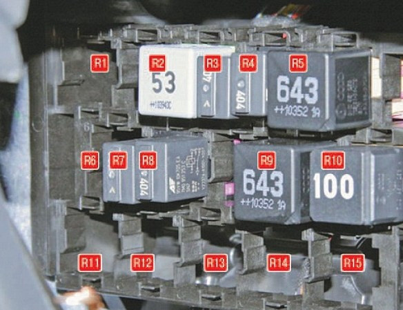
transcribed
- R1, R6, R11-R15 — reserve;
- R2 - windshield heating relay (depending on configuration);
- R3 - start blocking relay;
- R4 - fuel supply relay through the pressure line;
- R5 - power relay;
- R7 - relay front position lights;
- R8 - fuel pump relay;
- R9 - air conditioner relay;
- R10 - relay contact "X"
Block under the hood
The mounting block with fuses and fuses is located on the battery cover.
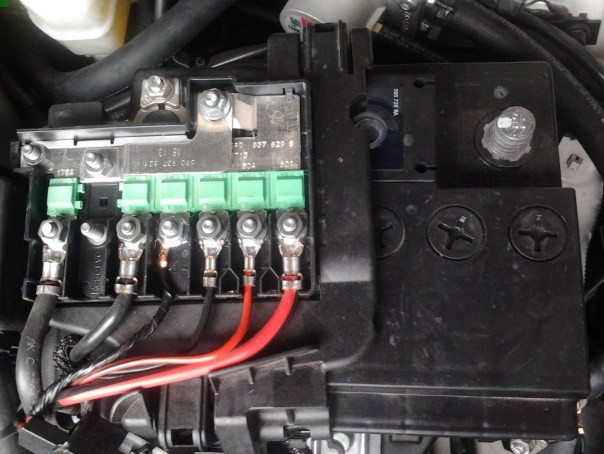
Option 1
scheme
Goal
- Generator 175A
- Not busy
- 80A Interior space
- 60A additional electrical heating
- 40A Interior space
- 50A Cooling fan, glow plugs
- Electric power steering 50A
- 25A ABS ESP ASR
- 30A cooling fan
- 5A cooling fan
- 40A ABS ESP ASR
- 5A Central control unit
- 5A automatic transmission, 40A additional heating
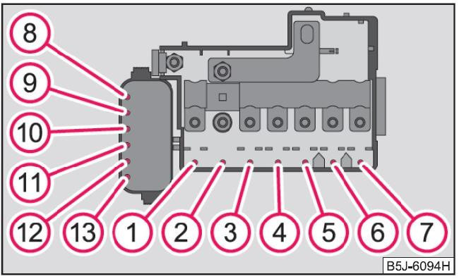
Option 2
scheme
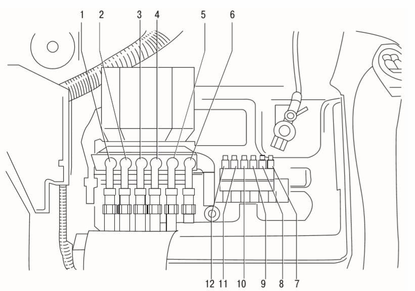
Description
| а | Generator 175A |
| two | Electrical switchboard 80A |
| 3 | 60A Additional heater |
| 4 | 40A Hydro - ABS electronic control unit |
| 5 | 50A Power steering control unit |
| 6 | Glow plugs 50A |
| 7 | 5A automatic transmission |
| 8 | Electrical switchboard 40A |
| 9 | 30A cooling fan |
| 10 | Conditioner 5A |
| 11 | 30A cooling fan |
| 12 | 25A Hydro - ABS electronic control unit |