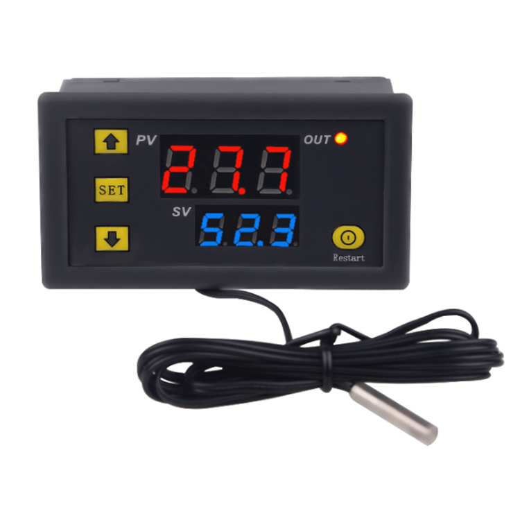
Thermostat with LED display
The system is used to maintain a certain temperature in a controlled room. In the proposed solution, the switch-on and switch-off temperature of the relay is set independently, due to which the setting possibilities are practically unlimited. The thermostat can operate both in heating mode and in cooling mode with any hysteresis range. For its design, only through elements and a ready-made waterproof temperature sensor were used. If desired, all this can fit in the Z-107 case, which is designed to be installed on the popular TH-35 "electric" bus.
Schematic diagram of the thermostat shown in fig. 1. The system must be supplied with a constant voltage of about 12 VDC, connected to connector X1. It can be any power source with a current load of at least 200 mA. Diode D1 protects the system from reverse polarity of the input voltage, and capacitors C1 ... C5 act as a mains filter. An external input voltage is applied to the regulator U1 type 7805. The thermometer is controlled by the U2 ATmega8 microcontroller, clocked by an internal clock signal, and the function of the temperature sensor is performed by the system type DS18B20.
It was used to communicate with the user three-digit LED display. The control is carried out multiplexed, the anodes of the display discharges are powered by transistors T1 ... T3, and the cathodes are controlled directly from the microcontroller port through limiting resistors R4 ... R11.
To enter the settings and configurations, the thermostat is equipped with buttons S1 ... S3. A relay was used as an executive system. When driving a heavy load, pay attention to the load on the relay contacts and PCB tracks. To increase their load capacity, you can tin the tracks or lay and solder copper wire to them.
thermostat must be assembled on two printed circuit boards, the assembly diagram of which is shown in Figure 2. The assembly of the system is typical and should not cause difficulties. It is carried out as standard, starting with soldering resistors and other small-sized elements to the driver board, and ending with the installation of electrolytic capacitors, a voltage stabilizer, relays and screw connections.
We mount the buttons and the display on the scoreboard. At this stage, and preferably before assembling the buttons and display, it is necessary to decide whether to the thermostat will be installed in the housing Z107.
If the thermostat will be mounted as standard, as in the title photo, then it is enough to connect both plates with an angle bar of goldpin pins. The view of the plates connected in this way is shown in photo 3. However, if we decide to install the thermostat in the Z107 case, as in photo 4, then a single simple 38 mm strip with gold pins with a female socket should be used to connect both plates. Drill three holes in the front panel of the case for the buttons S1…S3. To make the whole structure stable after assembly, you can additionally strengthen it with silver-plated wire (photo 5), additional protruding soldering pads will help here.
Last step temperature sensor connection. For this, a connector marked TEMP is used: the black wire of the sensor is connected to the pin marked GND, the yellow wire to the pin marked 1 W, and the red wire to the pin marked VCC. If the cable is too short, it can be extended using a twisted pair or shielded audio cable. The sensor connected in this way works properly even with a cable length of about 30 m.
After connecting the power supply, after a while the display will show the currently read temperature value. Whether the thermostat relay is energized indicates the presence of a dot in the last digit of the display. The thermostat adopts the following principle: in the heating mode, the object is automatically cooled, and in the cooling mode, it is automatically heated.