Fuel systems of gasoline and diesel engines
Content
The power system provides the main function of the power plant - the delivery of energy from the fuel tank to the internal combustion engine (ICE) that converts it into mechanical movement. It is important to develop it so that the engine always receives gasoline or diesel fuel in the right amount, no more and no less, in all the most diverse modes of operation. And if possible, save your parameters for as long as possible without losing the accuracy of the work.
Purpose and operation of the fuel system
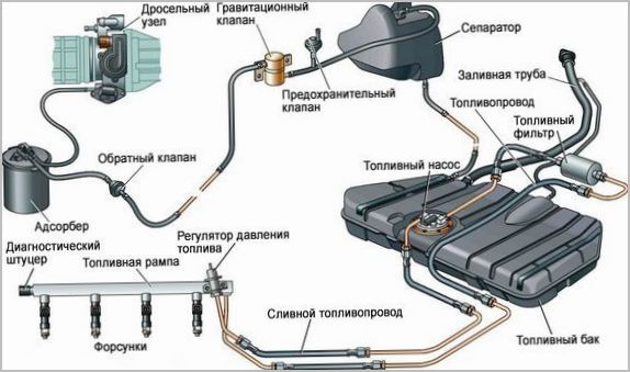
On an enlarged basis, the functions of the system are divided into transportation and dosing. The equipment for the first includes:
- a fuel tank where a supply of gasoline or diesel fuel is stored;
- booster pumps with different outlet pressures;
- filtration system for coarse and fine cleaning, with or without settling tanks;
- fuel lines from flexible and rigid hoses and pipelines with appropriate fittings;
- additional devices for ventilation, vapor recovery and safety in case of accidents.
Dosing of the required amount of fuel is performed by systems of different levels of complexity, these include:
- carburetors in obsolete engines;
- engine control units with a system of sensors and actuators;
- fuel injectors;
- high pressure pumps with dosing functions;
- mechanical and hydraulic controls.
Fuel supply is closely related to providing the engine with air, but still these are different systems, so the connection between them is carried out only through electronic controllers and the intake manifold.
Organization of the supply of gasoline
Two systems are fundamentally different that are responsible for the correct composition of the working mixture - carburetor, where the rate of gasoline supply is determined by the speed of the air flow sucked in by the pistons, and injection under pressure, where the system only monitors the air flow and engine modes, dosing fuel on its own.
Carburetor
The supply of gasoline with the help of carburetors is already outdated, since it is impossible to comply with environmental standards with it. Even the use of electronic or vacuum systems in carburetors did not help. Now these devices are not used.

The principle of operation of the carburetor was to pass through its diffusers an air flow directed to the intake manifold. Special profiled narrowing of the diffusers caused a decrease in pressure in the air jet relative to atmospheric pressure. Due to the resulting drop, gasoline was supplied from the sprayers. Its quantity was limited by the creation of a fuel emulsion in the composition determined by the combination of fuel and air jets.
The carburetors were controlled by small changes in pressure depending on the flow rate, only the fuel level in the float chamber was constant, which was maintained by pumping and closing the inlet shut-off valve. There were many systems in carburetors, each of which was responsible for its own engine mode, from start-up to rated power. All this worked, but the quality of dosing eventually became unsatisfactory. It was impossible to precisely adjust the mixture, which was necessary for the emerging exhaust gas catalytic converters.
Fuel injection
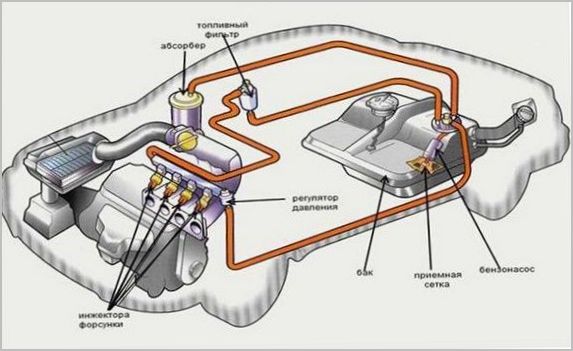
Fixed pressure injection has fundamental advantages. It is created by an electric pump installed in the tank with an integrated or remote regulator and is maintained with the required accuracy. Its value is of the order of several atmospheres.
Gasoline is supplied to the engine by injectors, which are solenoid valves with atomizers. They open when they receive a signal from the electronic engine control system (ECM), and after a calculated time they close, releasing exactly as much fuel as is required for one engine cycle.
Initially, a single nozzle was used, located in place of the carburetor. Such a system was called central or single injection. Not all shortcomings have been eliminated, so more modern structures have separate nozzles for each cylinder.
Distributed and direct (direct) injection systems are divided according to the location of the nozzles. In the first case, the injectors supply fuel to the intake manifold, close to the valve. In this zone, the temperature is increased. A short path to the combustion chamber does not allow gasoline to condense, which was a problem with single injection. In addition, it became possible to phase the flow, releasing gasoline strictly at the moment the intake valve of a particular cylinder opens.
The direct injection system works even more efficiently. When the nozzles are located in the heads and directly introduced into the combustion chamber, it is possible to use the most modern methods of multiple injection in one or two cycles, layered ignition and complex swirling of the mixture. This increases efficiency, but creates reliability problems that lead to higher cost of parts and assemblies. In particular, we need a high-pressure pump (high pressure fuel pump), special nozzles and ensuring that the intake tract is cleaned of contaminants by the recirculation system, because now gasoline is not supplied to the intake.
Fuel equipment for diesel engines
Operation with compression ignition HFO has its own specifics associated with the difficulties of fine atomization and high diesel compression. Therefore, fuel equipment has little in common with gasoline engines.
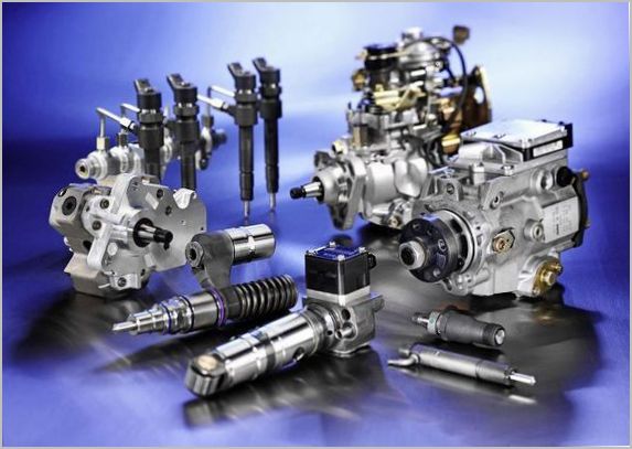
Separate injection pump and unit injectors
The high pressure required for high-quality injection into highly compressed hot air is created by high-pressure fuel pumps. According to the classical scheme, to its plungers, that is, piston pairs made with minimal clearances, fuel is supplied by a booster pump after thorough cleaning. The plungers are driven by the engine through a camshaft. The same pump performs dosing by turning the plungers through a gear rack connected to the pedal, and the moment of injection is determined due to synchronization with the gas distribution shafts and the presence of additional automatic regulators.
Each plunger pair is connected by a high-pressure fuel line to injectors, which are simple spring-loaded valves led into the combustion chambers. To simplify the design, so-called pump-injectors are sometimes used, which combine the functions of high-pressure fuel pumps and sprayers due to the power drive from the camshaft cams. They have their own plungers and valves.
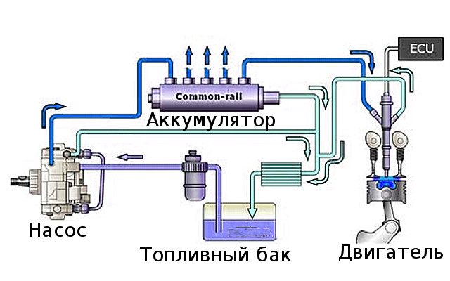
Main injection type Common Rail
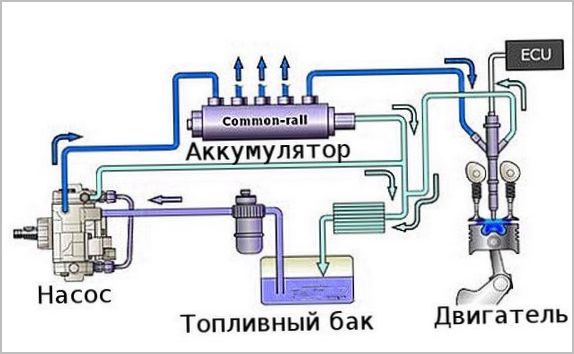
The principle of electronic control of nozzles connected to a common high-pressure line has become more perfect. Each of them has an electro-hydraulic or piezoelectric valve that opens and closes at the command of the electronic unit. The role of the injection pump is reduced only to maintaining the required pressure in the rail, which, with this principle, could be brought up to 2000 atmospheres or more. This made it possible to more accurately control the engine and fit it into the new toxicity standards.
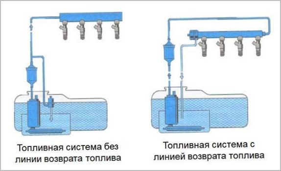
Application of fuel return lines
In addition to the direct supply of fuel to the engine compartment, sometimes a return drain is also used through a separate return line. This has various purposes, from facilitating the regulation of pressure at different points in the system, to the organization of continuous circulation of fuel. Recently, backflow into the tank is rarely used, usually it is needed only for solving local problems, for example, controlling the hydraulics of direct injection nozzles.