Transport Fuel - Booster Pump
Content
 The fuel pump or fuel delivery pump is a component of the engine's fuel circuit that transports fuel from the tank to other parts of the fuel circuit. Today, these are mainly injection pumps (high pressure) - direct injection engines. In older engines (gasoline indirect injection) it was a direct injector or even in older cars a carburetor (float chamber).
The fuel pump in cars can be driven mechanically, hydraulically or electrically.
Mechanically Driven Fuel Pumps
Diaphragm pump
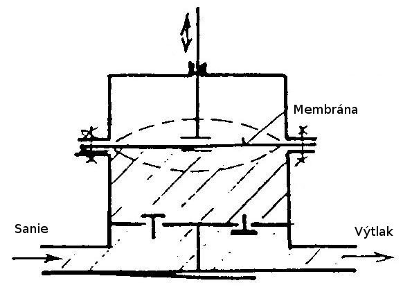
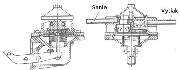
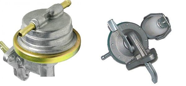
Older gasoline engines equipped with carburetors usually use a diaphragm pump (discharge pressure 0,02 to 0,03 MPa), which is mechanically controlled by an eccentric mechanism (pusher, lever and eccentric). When the carburetor is sufficiently filled with fuel, the float chamber needle valve closes, the pump outlet valve opens, and the discharge line remains pressurized to hold the diaphragm in the extreme position of the mechanism. Fuel transport has been interrupted. Even if the eccentric mechanism is still running (even when the engine is running), the spring that fixes the discharge stroke of the pump diaphragm remains compressed. When the needle valve opens, the pressure in the pump discharge line drops, and the diaphragm, pushed by the spring, makes a discharge stroke, which again rests on the pusher or the lever of the eccentric control mechanism, which compresses the spring together with the diaphragm and sucks fuel from the tank into the float chamber.
gear pump
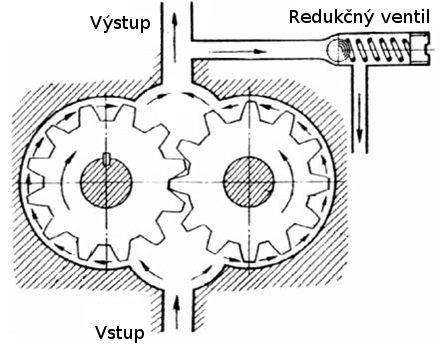
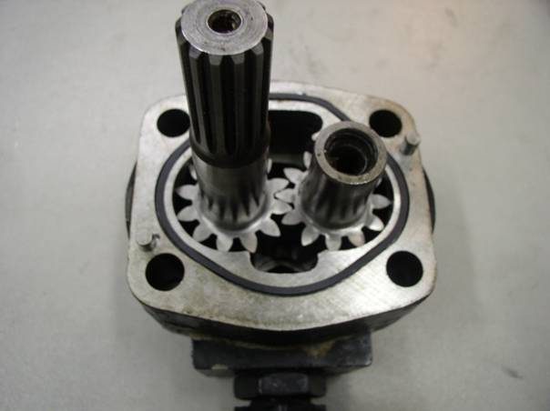
The gear pump can also be mechanically driven. It is located either directly in the high pressure pump, where it shares the drive with it, or is located separately and has its own mechanical drive. The gear pump is driven mechanically via a clutch, gear or toothed belt. The gear pump is simple, small in size, light in weight and highly reliable. Typically, an internal gear pump is used, which, due to the special gearing, does not require any additional sealing elements to seal the individual spaces (chambers) between the teeth and the gaps between the teeth. The basis is two jointly engaged gears rotating in opposite directions. They transport the fuel between the tines from the suction side to the pressure side. The contact surface between the wheels prevents fuel return. The inner outer gear wheel is connected to a mechanically driven (engine driven) shaft which drives the outer inner gear wheel. The teeth form closed transport chambers that cyclically decrease and increase. The enlargement chambers are connected to the inlet (suction) opening, the reduction chambers are connected to the outlet (discharge) opening. The pump with an internal gearbox operates with a discharge pressure of up to 0,65 MPa. The speed of the pump, and therefore the amount of fuel transported, depends on the speed of the engine and is therefore controlled by a throttle valve on the suction side or a pressure relief valve on the pressure side.
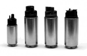
Electrically driven fuel pumps
By location, they are divided into:
- in-line pumps,
- pumps in the fuel tank (in-tank).
In-Line means the pump can be located virtually anywhere on the low pressure fuel line. The advantage is an easier replacement-repair in the event of a breakdown, the disadvantage is the need for a suitable and safe place in the event of a breakdown - a fuel leak. The submersible pump (In-Tank) is a removable part of the fuel tank. It is mounted on top of the tank and is usually part of the fuel module, which includes, for example, a fuel filter, a submersible container and a fuel level sensor.
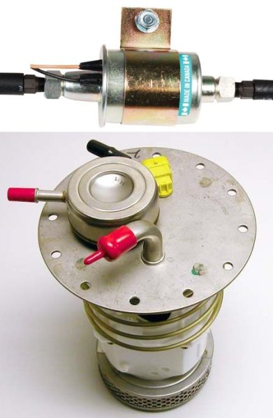
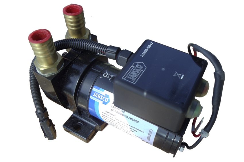
The electric fuel pump is most often located in the fuel tank. It takes fuel from the tank and supplies it to the high pressure pump (direct injection) or to the injectors. It must ensure that, even in extreme situations (wide open throttle operation at high outside temperatures), bubbles do not form in the fuel supply line due to the high vacuum. As a result, there should be no engine malfunctions due to the appearance of fuel bubbles. Bubble vapors are vented back to the fuel tank through the pump vent. The electric pump is activated when the ignition is turned on (or the driver's door is opened). The pump runs for about 2 seconds and builds up overpressure in the fuel line. During heating in the case of diesel engines, the pump is switched off so as not to overload the battery unnecessarily. The pump starts up again as soon as the engine starts. Electrically driven fuel pumps can be connected to a vehicle immobilizer or alarm system and are controlled by a control unit. Thus, the control unit blocks the activation (voltage supply) of the fuel pump in the event of unauthorized use of the vehicle.
The electric fuel pump has three main parts:
- electric motor
- sam nasos,
- connecting cover.
The connection cover has built-in electrical connections and a union for injecting the fuel line. It also includes a non-return valve that keeps diesel in the fuel line even after the fuel pump is turned off.
In terms of design, we divide fuel pumps into:
- dental
- centrifugal (with side channels),
- screw,
- wing.
Gear pump
An electrically driven gear pump is structurally similar to a mechanically driven gear pump. The inner outer wheel is connected to an electric motor that drives the outer inner wheel.
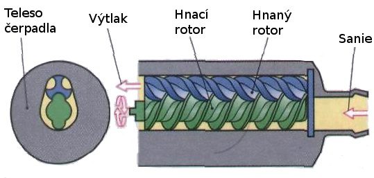
Screw pump
In this type of pump, fuel is sucked in and discharged by a pair of counter-rotating helical gear rotors. The rotors engage with very little lateral play and are longitudinally mounted in the pump casing. The relative rotation of the toothed rotors creates a variable volume transport space that moves smoothly in the axial direction as the rotors rotate. In the area of the fuel inlet, the transport space increases, and in the area of the outlet, it decreases, which creates a discharge pressure of up to 0,4 MPa. Due to its design, the screw pump is often used as a flow pump.
Vane roller pump
An eccentrically mounted rotor (disk) is installed in the pump casing, which has radial grooves around its circumference. In the grooves, rollers are installed with the possibility of sliding, forming the so-called rotor wings. When it rotates, a centrifugal force is created, pressing the rollers against the inside of the pump housing. Each groove guides one roller freely, the rollers acting as a circulation seal. A closed space (camera) is created between the two rollers and the orbit. These spaces cyclically increase (fuel is sucked in) and decreases (displaced from the fuel). Thus, the fuel is transported from the inlet (intake) port to the outlet (outlet) port. The vane pump provides a discharge pressure of up to 0,65 MPa. The electric roller pump is mainly used in passenger cars and light commercial vehicles. Due to its design, it is suitable for use as an in-tank pump and is located directly in the tank.
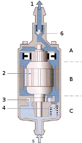
A - connecting cap, B - electric motor, C - pumping element, 1 - outlet, discharge, 2 - motor armature, 3 - pumping element, 4 - pressure limiter, 5 - inlet, suction, 6 - check valve.
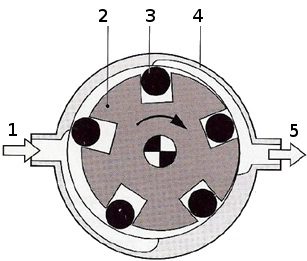
1 - suction, 2 - rotor, 3 - roller, 4 - base plate, 5 - outlet, discharge.
Centrifugal pump
A rotor with blades is installed in the pump housing, which moves the fuel from the center to the circumference by rotation and subsequent action of centrifugal forces. The pressure in the side pressure channel increases continuously, i.e. practically without fluctuations (pulsations) and reaches 0,2 MPa. This type of pump is used as the first stage (pre-stage) in the case of a two-stage pump to create pressure for degassing the fuel. In the case of a stand-alone installation, a centrifugal pump with a large number of rotor blades is used, which provides a discharge pressure of up to 0,4 MPa.
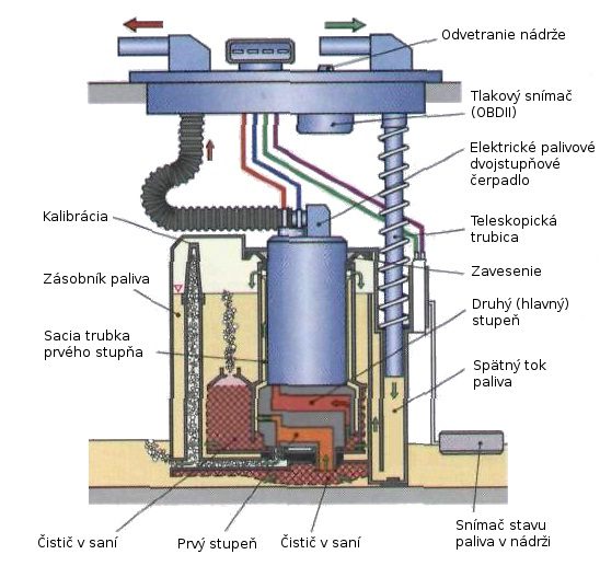
Two-stage fuel pump
In practice, you can also find a two-stage fuel pump. This system combines different types of pumps into one fuel pump. The first stage of the fuel pump usually consists of a low pressure centrifugal pump that draws in the fuel and creates a slight pressure, thereby degassing the fuel. The head of the low pressure pump of the first stage is introduced into the inlet (suction) of the second pump with a higher outlet pressure. The second - the main pump is usually geared, and at its outlet the necessary fuel pressure is created for a given fuel system. Between the pumps (discharge of the 1st pump with suction of the 2nd pump) there is a built-in overpressure relief valve to prevent hydraulic overload of the main fuel pump.
Hydraulic driven pumps
This type of pump is mainly used in complex - fragmented fuel tanks. This is because in a fragmented tank it can happen that during refueling (on a curve) fuel can overflow to places beyond the suction reach of the fuel pump, so it is often necessary to transfer fuel from one part of the tank to another. . For this, for example, an ejector pump. The fuel flow from the electric fuel pump draws fuel from the side chamber of the fuel tank through the ejector nozzle and then transports it further to the transfer tank.
Fuel pump accessories
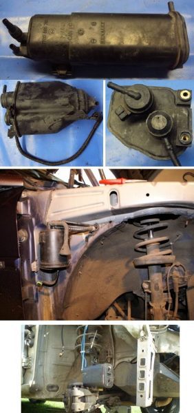
Fuel cooling
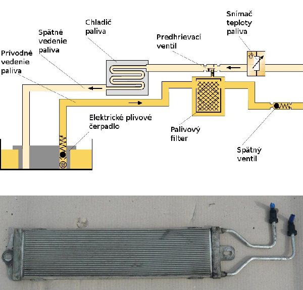
In PD and Common Rail injection systems, the spent fuel can reach significant temperatures due to high pressure, therefore it is necessary to cool this fuel before returning to the fuel tank. Fuel that is too hot returning to the fuel tank can damage both the tank and the fuel level sensor. The fuel is cooled in a fuel cooler located under the vehicle floor. The fuel cooler has a system of longitudinally directed channels through which the returned fuel flows. The radiator itself is cooled by air that flows around the radiator.
Exhaust valves, activated carbon canister
Gasoline is a highly volatile liquid, and when it is poured into the tank and passed through the pump, gasoline vapors and bubbles form. To prevent these fuel vapors from escaping from the tank and blending equipment, a closed fuel system equipped with an activated carbon bottle is used. Gasoline vapors that form during operation, but also when the engine is switched off, cannot escape directly into the environment, but are captured and filtered through an activated charcoal container. Activated carbon has a huge area (1 gram about 1000 m) due to its very porous shape.2) which captures gaseous fuel - gasoline. When the engine is running, negative pressure is created by a thin hose that extends from the engine inlet. Due to the vacuum, part of the intake air passes from the suction container through the activated carbon container. The stored hydrocarbons are sucked out, and the sucked-in liquefied fuel is fed back into the tank through the regeneration valve. The work, of course, is controlled by the control unit.