U023A Lost Communication With Image Processing Module A
Content
U023A Lost Communication With Image Processing Module A
OBD-II DTC Datasheet
Lost Communication with Image Processing Module A
What does this mean?
This is a generic communications system diagnostic trouble code that applies to most makes and models of OBD-II vehicles.
This code means that imaging module A (IPA-A) and other control modules on the vehicle do not communicate with each other. The circuitry most commonly used for communication is known as Controller Area Bus communication, or simply the CAN bus.
Modules communicate with each other over a network, just like the network you have at home or work. Car manufacturers use several networked systems. Prior to 2004, the most common (non-exhaustive) inter-module communication systems were the serial communication interface, or SCI; SAE J1850 or PCI bus; and Chrysler Collision Detection, or CCD. The most common system used after 2004 is known as Controller Area Network communication, or simply the CAN bus (also used until 2004 on a small segment of vehicles). Without this CAN bus, control modules cannot communicate and your scan tool may or may not receive information from the vehicle, depending on which circuit is affected.
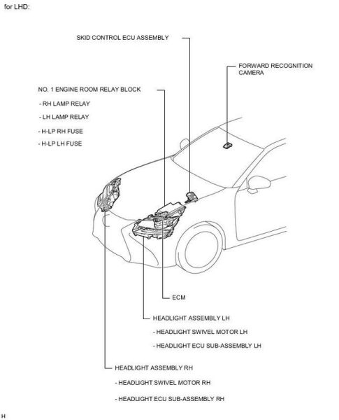
Imaging Module A (IPA-A) is usually located behind the dashboard on either side of the vehicle. It can also be installed behind the grille along with the front camera. It receives input from a variety of sensors, some of which are directly connected to it, and most are sent over a bus communication system from the powertrain control module (PCM). These inputs allow the module to control vehicle braking when another vehicle approaches from the side; also when the speed of approach between the towed vehicle and the driving cab becomes too close; when someone approaches the vehicle from the front. Refer to your specific vehicle handbook to determine which door is labeled “A” in your specific case.
Troubleshooting steps may vary depending on the manufacturer, the type of communication system, the number of wires, and the colors of the wires in the communication system.
Code severity and symptoms
The seriousness in this case is never serious, as this is a device for the convenience of customers, and in the event of a complete power failure, there is always a manual workaround. If the IPA-A does not work, it will in no way affect the operation of the vehicle.
Symptoms of a U023A code may include:
- IPM-A does not turn on / does not work - the fault indicator is on
- ABS warning light is on
- Red brake warning light on - ESC/ESP warning light on
reasons
Usually the reason for installing this code is:
- Open on CAN bus + or - circuit
- Short to ground or ground in any CAN bus circuit
- No power or ground to the IPA-A module
- Rarely - the control module is faulty
Diagnostic and repair procedures
A good place to start with ALL electrical diagnostics is to check the Technical Service Bulletins (TSB) for your vehicle. The problem you are facing may be known to others in the field. A known fix may have been released by the manufacturer and can save you time and money during diagnostics.
It is assumed that a code reader is available to you at this point, as you may have been able to access the codes up until now. See if there were any other DTCs related to bus communication or battery / ignition. If so, you should diagnose them first, as misdiagnosis is known to occur if you diagnose the U023A code before any of the underlying codes are thoroughly diagnosed and corrected.
If the only code you get from other modules is U023A, try accessing IPA-A. If you can access the codes from the IPA-A, then the U023A code is either intermittent or a memory code. If you cannot access the IPA-A, then the code U023A set by other modules is active and the problem already exists.
The most common failure is a circuit failure that results in loss of power or ground to the imaging module a.
Check all fuses supplying the IPA-A module on this vehicle. Check out all the reasons for IPA-A. Locate ground anchorage points on the vehicle and make sure these connections are clean and secure. If necessary, remove them, take a small wire bristle brush and baking soda / water solution and clean each one, both the connector and the place where it connects.
If any repairs have been made, clear the diagnostic trouble codes from any modules that set the code in memory and see if you can now communicate with the IPA-A module. If communication with the IPA-A recovers, the problem is most likely a fuse / connection issue.
If the code returns or communication with the module still fails, look for the CAN bus communication connections on your vehicle, especially the IPA-A connector, which is usually located behind the dashboard on both sides of the vehicle. can also be installed behind the grille along with the front camera. Disconnect the negative battery cable before disconnecting the connector from the IPA-A. Once detected, visually inspect the connectors and wiring. Look for scratches, scuffs, exposed wires, burn marks, or molten plastic.
Disconnect the connectors and carefully inspect the terminals (metal parts) inside the connectors. See if they look burnt or have a green tint indicating corrosion. If you need to clean the terminals, use an electrical contact cleaner and a plastic bristle brush. Allow to dry and apply electrical grease where the terminals touch.
Before reconnecting the connectors to the IPA-A, do these few voltage checks. You will need access to a digital volt/ohmmeter (DVOM). Make sure the IPA-A has power and ground. Access the electrical diagram and determine where the main power and ground supplies enter the IPA-A. Connect the battery before continuing with the IPA-A still disconnected. Connect the red lead of your voltmeter to each B+ (battery voltage) power supply included in the IPA-A connector, and the black lead of your voltmeter to a good ground (if unsure, battery negative always works). You should see the battery voltage reading. Make sure you have a good reason. Connect the red lead of the voltmeter to the battery positive (B+) and the black lead to each ground circuit. Once again, you should see the battery voltage every time you connect. If not, repair the power or ground circuit.
Then check the two communication circuits. Locate CAN C+ (or HSCAN+) and CAN C- (or HSCAN - circuit). With the black wire of the voltmeter connected to a good ground, connect the red wire to CAN C+. With the key on and engine off, you should see about 2.6 volts with little fluctuation. Then connect the red wire of the voltmeter to the CAN C- circuit. You should see about 2.4 volts with little fluctuation. Other manufacturers show CAN C- at about 5V and an oscillating key with the engine off. Check your manufacturer's specifications.
If all tests pass and communication is still not possible, or you were unable to reset DTC U023A, the only thing to do is to seek help from a trained automotive diagnostician, as this will indicate an IPA-A failure. . Most of these IPA-A's must be programmed or calibrated to fit properly in a vehicle.
Related DTC discussions
- There are currently no related topics in our forums. Post a new topic on the forum now.
Need more help with code U023A?
If you still need help with DTC U023A, post your question in the comments below this article.
NOTE. This information is provided for informational purposes only. It is not intended to be used as a repair recommendation and we are not responsible for any action you take on any vehicle. All information on this site is protected by copyright.