Tutorial: checking electrical and electronic circuits
Content
We will see how to detect and solve problems in the electrical circuit of the battery, electric starter, ignition and lighting. With a multimeter and appropriate instructions, this task is not that difficult. This mechanic guide is brought to you at Louis-Moto.fr.
If you are in doubt about your knowledge of electricity, we advise you to click here before starting this tutorial. To find out how to check your electrical and electronic circuits, follow this link.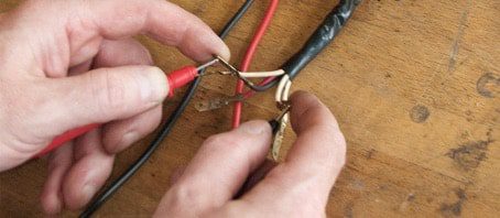
Checking the electrical circuits of the motorcycle
When the electric starter reacts sluggishly, vital sparks collect, headlights go out and fuses blow out at an alarming rate, this is a state of emergency for many bikers. While mechanical faults are detected quickly, electrical faults, on the other hand, are invisible, hidden, silent and often result in damage to the entire vehicle. However, with a little patience, a multimeter (even a cheap one), and a few instructions, you don't need to be an automotive electronics expert to track down such errors and save you high repair shop costs.
For ignition, lighting, starter and various other functions, most motorcycles (with the exception of a few enduros and older models of mopeds or mopeds) draw power from the battery. If the battery is discharged, these vehicles will be more difficult to drive.
In principle, a discharged battery can have two causes: either the charging current circuit no longer charges the battery sufficiently while driving, or a current failure somewhere in the electrical circuit. If there are signs of insufficient charging of the battery by the alternator (for example, the starter reacts sluggishly, the main headlight dims while driving, the charge indicator flashes), provide access to all components of the charging circuit for visual inspection: plug connectors The connection between the alternator and the regulator must be securely and neatly connected , the corresponding cables must not show signs of breakage, abrasion, fire or corrosion (“infected” with green rust), the battery connection must also show no signs of corrosion (if (necessary, clean the surface with a knife and apply lubricant to the terminals), the generator and the regulator / rectifier should not have visible mechanical defects.
Keep inspecting the various components, the battery should be in good condition and fully charged. If there is a malfunction in one of the components in the charging circuit, also check all other components in that circuit to make sure they are not damaged.
Checking the charging circuit - let's get started
01 - Charging voltage
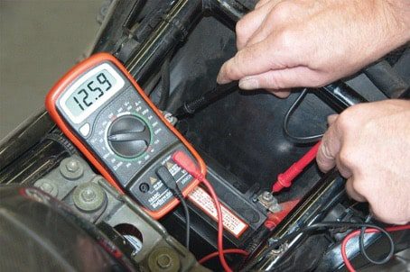
Measuring the battery charging voltage indicates whether the charging circuit is working properly. Raise the vehicle (preferably a warm engine) and make sure you have access to the battery terminals. For 12-volt electrical systems, set the multimeter to a 20 V (DC) measuring range first and connect it to the positive and negative terminals of the battery.
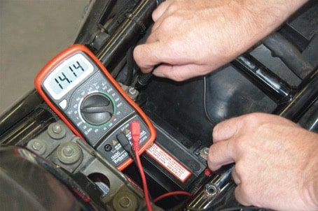
If the battery is in good condition, the idle voltage should be between 12,5 and 12,8 V. Start the engine and increase the speed until it reaches 3 rpm. If the load circuit is healthy, the voltage should now increase until it reaches the limit value, but does not exceed it.
 Depending on the vehicle, this limit is between 13,5 and 15 V; for the exact value refer to the service manual for your car model. If this value is exceeded, the voltage regulator (which often forms a unit with a rectifier) fails and no longer regulates the load voltage correctly. This can lead, for example, to leakage of acid from the battery ("overflow") and, over time, to damage to the battery due to overcharging.
Display of transient voltage peaks indicates a rectifier and / or generator malfunction. If, despite increasing engine speed, you do not notice an increase in voltage, the alternator may not be providing sufficient charging current; then it needs to be checked.
02 – Checking the generator
Start by identifying the type of alternator installed in your vehicle and then check the following points:
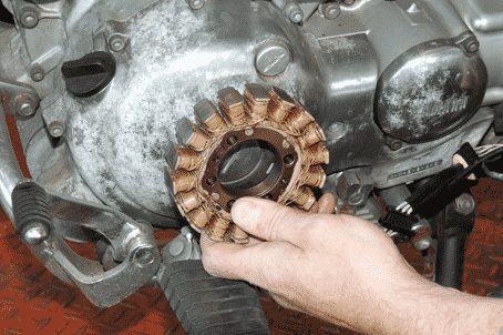
Controlling a permanent magnet rotor radial alternator
Star-mounted alternators operate with a permanent magnet rotor that rotates to energize the outer stator windings. They run in an oil bath, most of the time on the crankshaft journal. Most often, malfunctions occur with constant overload or overheating of the regulator.
Checking unrectified charging voltage
Stop the engine and switch off the ignition. Disconnect the alternator harness from the regulator / rectifier. Then measure the voltage directly at the generator (preselect the measuring range up to 200 VAC).
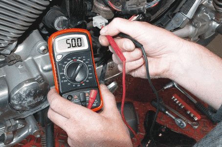
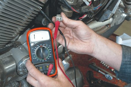
Connect the two pins of the generator connector respectively to the test leads of the multimeter. Run the engine for approximately 3 to 000 rpm.
Measure the voltage, stop the motor, connect the test leads to a different combination of connections, restart the motor for another measurement, etc. until you have checked all possible combinations. If the measured values are the same (a mid-size motorcycle generator typically outputs between 50 and 70 volts; see the service manual for your car model for exact values), the generator is operating normally. If one of the measured values is significantly lower, then it is defective.
Check for open and short to ground
If the alternator does not provide sufficient charging voltage, it is possible that the winding is broken or there is a winding short to ground. Measure the resistance to find such a problem. To do this, stop the engine and turn off the ignition. Set the multimeter to measure resistance and select a measurement range of 200 ohms. Press the black test lead to the ground, press the red test lead in sequence to each pin of the alternator connector. An open circuit (infinite resistance) should not be fixed - otherwise the stator will short circuit to ground.
Open circuit supervision
Then check all possible combinations of pins with each other using the test leads - the measured resistance should always be low and uniform (usually <1 ohm; see the appropriate repair manual for your car model for the exact value).
If the measured value is too large, the passage between the windings is insufficient; if the measured value is 0 ohm, short circuit - in both cases the stator is faulty. If the alternator windings are in good condition, but the alternator voltage at the alternator is too low, the rotor is probably demagnetized.
Regulator / rectifier
If the voltage measured at the battery exceeds the factory-set vehicle limit when the engine speed is increased (depending on the vehicle model, the voltage must be between 13,5 and 15 V), the governor voltage is faulty (see Step 1). or needs to be reconfigured.
Only old and classic models are still equipped with this adjustable regulator model - if the battery is not sufficiently charged and the measured values of the unrectified voltage are correct, you need to re-adjust.
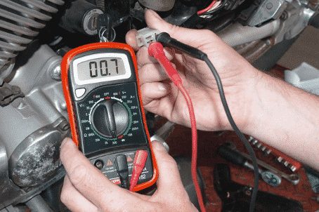
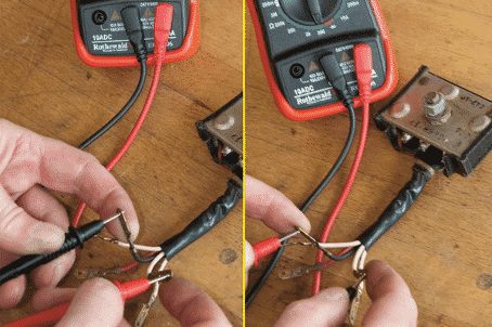
To test a single rectifier, first disconnect it from the electrical circuit. Set the multimeter to measure resistance and select a measuring range of 200 ohms. Then measure the resistance between the rectifier ground wire and all connections to the generator, and between the Plus output cable and all connections in both directions (so the polarity must be reversed once accordingly).
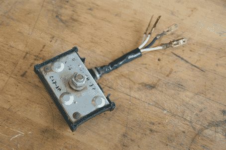
You should measure a low value in one direction and a value at least 10 times higher in the other (see Photo 7). If you measure the same value in both directions with the connection option (i.e. despite reversed polarity), the rectifier is defective and must be replaced.
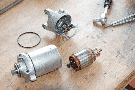
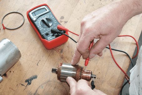
Checking the collector generator
Collector generators do not supply current through permanent magnets, but due to the electromagnetism of the external excitation winding. The current is removed from the rotor collector by carbon brushes. This type of generator always runs dry, either on the crankshaft side with an external governor, or as a stand-alone unit, usually equipped with an integral governor. In most cases, faults are caused by vibrations or jolts caused by lateral rotor acceleration or thermal stress. Carbon brushes and collectors wear out over time.
Disassemble generators with separate manifolds, preferably from a motorcycle, before performing a general inspection (disconnect the battery first) and then dismantle them.
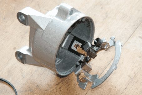
Insufficient generator power can be caused, for example, by wear on the collector. So, start by checking the force applied by the brush springs, then the length of the carbon brushes (replace worn parts if necessary). Clean the manifold with gasoline or brake cleaner (degreased); if necessary, touch up with fine-grained emery paper. The depth of the manifold grooves should be between 0,5 and 1 mm. ; if necessary, rework them with a saw blade or replace the rotor when the wear limit of the slip ring has already been reached.
To check for a short to ground and an open stator winding, set the multimeter to measure resistance and select a measurement range of 200 ohms. Hold the test lead before and the test lead after the field winding respectively - you should measure low resistance (<1 ohm; see the owner's manual for your car model for the exact value). If the resistance is too high, the circuit is interrupted. To test for a short to ground, select a high measurement range (Ω). Press the red test lead against the stator winding and the black test lead against the housing (ground). You must measure infinite resistance; otherwise, a short circuit to ground (short circuit). Now measure the resistances between the two rotor commutator blades, respectively, with all possible combinations (measurement range: another 200 ohms). A low resistance should always be measured (an order of magnitude is often between 2 and 4 ohms; see the repair manual corresponding to your car model for the exact value); when it is zero, a short circuit occurs; if the resistance is high, the circuit is interrupted and the rotor needs to be replaced.
To test for a short to ground, select the high measuring range (Ω) again. Hold the red test lead against the lamella on the manifold and the black test lead against the axis (ground) respectively. You must measure the infinite resistance accordingly; otherwise, short circuit to ground (faulty rotor).
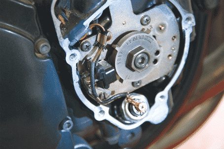
You do not need to disassemble the assembled alternator manifold. on the end of the crankshaft for inspection. To inspect the manifold, rotor and stator, all you have to do is disconnect the battery and remove the alternator cover.
The manifold has no grooves. Poor generator performance can be caused by oil contamination in the manifold, worn carbon brushes, or defective compression springs. The generator compartment must be free of engine oil or rainwater (replace appropriate gaskets if necessary). Check the stator windings for open or short to ground in the appropriate wire connections as described above. Directly check the rotor windings between the two copper tracks of the collector (proceed as described). You should measure low resistance (approximately 2 to 6 ohms; see the workshop manual for your car model for exact values); when it is zero, a short circuit occurs; at high resistance, the winding breaks. On the other hand, the resistance measured against ground must be infinitely large.
Regulator / rectifier : see step 2.
If the alternator is defective, you need to consider whether it is worth taking the repair to a specialized workshop or buying an expensive original part, or whether you can get a good used part. Working / monitored condition with warranty from the respective supplier ... sometimes it can be advantageous to compare prices.
Checking the ignition circuit of the battery - let's get started
01 - Ignition coils, spark plug leads, ignition cables, spark plugs
If the motorcycle does not want to start when the starter motor cranks the engine and the mixture of gasoline and air in the engine is correct (the spark plug gets wet), the problem is due to a malfunction in the electrical circuit of the engine. ... If there is a low energy ignition spark or no spark at all, first visually inspect wire connections, spark plugs, and spark plug terminals. It is advisable to replace very old spark plugs, terminals and ignition cables directly. Use iridium spark plugs for improved starting performance (greatly improved free combustion, more powerful spark plug). If the coil body has small streaks that look charred, these may be current leakage lines due to contamination or fatigue of the coil body material (clean or replace).
Moisture can also enter the ignition coil through invisible cracks and cause short circuits. It often happens that old ignition coils fail when the engine is hot and they start working again as soon as it gets cold, in which case all you have to do is replace components.
To check the quality of the ignition spark, you can check the spark gap with a tester.
When the spark is strong enough, it should be able to travel at least 5-7mm from the ignition wire to ground (when the coil condition is really good, the spark can travel at least 10mm). ... It is not recommended to allow the spark to travel to the ground of the engine without a spark gap tester to avoid damaging the ignition box and to avoid the risk of electric shock when holding the cable in your hand.
A low power ignition spark (especially in older vehicles) can be explained by a voltage drop in the ignition circuit (eg if the wire is corroded - see below for verification). In case of doubt, we recommend having the ignition coils checked by a specialist workshop.
02 - Ignition box
If the spark plugs, spark plug terminals, ignition coils, and wire connectors are OK when the spark is missing, then the ignition box or its controls are faulty (see below). The ignition box, unfortunately, is an expensive sensitive element. Therefore, it should only be checked in a specialized garage using a suitable special tester. At home, you can only check if the cable connections are in perfect condition.
A rotor pin, usually mounted on the crankshaft journal and triggering a coil with a pulse generator ("slip coil"), sends a pulse to electronic ignition systems. You can check the collector coil with a multimeter.
Select the 2 kΩ measurement range for resistance measurement. Disconnect the slip coil, press the measuring tips against the fittings and compare the measured value with the repair manual for your car model. A resistance that is too high indicates an interruption, and a resistance that is too low indicates a short circuit. Then set your multimeter to 2MΩ range and then measure the resistance between winding and ground - if not "infinite" then short to ground and coil should be replaced.
Checking the starter circuit - let's go
01 - Starter relay
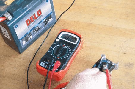
If you hear clicking or humming when you try to start, when the starter does not crank the engine and the battery is well charged, the starter relay is probably bad. The starter relay discharges the wiring and the starter circuit switch. To check, remove the relay. Set the multimeter to measure resistance (measurement range: 200 ohms). Connect the test leads to the thick connector on the battery and the thick connector to the starter. Hold the minus connection of a fully charged 12V battery on the negative side of the relay (see Wiring Diagram for the relevant motorcycle model) and the positive connection on the positive side of the relay (see Wiring Diagram - usually connection to the start button).
The relay should now "click" and you should measure 0 ohms.
If the resistance is significantly greater than 0 ohms, the relay is faulty even if it breaks. If the relay does not burn out, it must also be replaced. If you can find the settings in the workshop manual for your car model, you can also check the internal resistance of the relay with an ohmmeter. To do this, hold the test tips of the tester on the precise relay connections and read the value.
02 – Starter
If the starter does not work with a working starter relay and a fully charged battery, inspect the starter button; on older vehicles, contact is often interrupted due to corrosion. In this case, clean the surface with sandpaper and a little contact spray. Check the start button by measuring the resistance with a multimeter with the cable glands disconnected. If you measure a resistance greater than 0 ohms, the switch does not work (clean again, then measure again).
To check the starter, disconnect it from the motorcycle (remove the battery), then disassemble it.
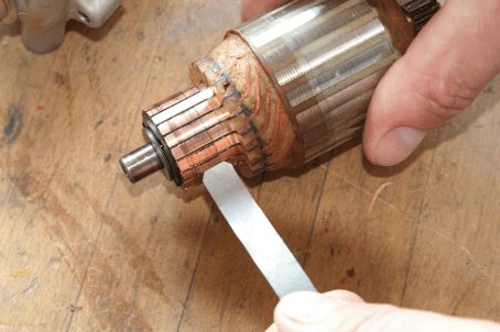
Start by checking the force applied by the brush springs and the length of the carbon brush (replace worn carbon brushes). Clean the manifold with gasoline or brake cleaner (degreased); if necessary, touch up with fine-grained emery paper.
The depth of the manifold grooves should be between 0,5 and 1 mm. ; cut them with a thin saw blade if necessary (or replace the rotor).
To check for short to ground and open circuit, first carry out the described alternator resistance measurement: first set the multimeter to a measuring range of 200 ohms and, accordingly, measure the resistance between the two blades of the rotor collector with all possible combinations.
Low resistance should always be measured (<1 ohm - refer to the repair manual for your vehicle model for the exact value).
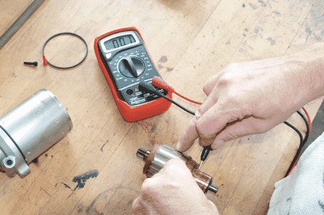
When the resistance is too high, the circuit breaks and the rotor fails. Then select a measurement range of up to 2 MΩ on the multimeter. Hold the red test lead against the lamella on the manifold and the black test lead against the axis (ground) respectively. You must measure the infinite resistance accordingly; otherwise, a short circuit to ground occurs and the rotor is also faulty.
If the starter stator is equipped with field windings instead of permanent magnets, also check that there is no short circuit to ground (if the resistance between ground and field winding is not infinite, replace the winding) and check for open circuit. (resistance inside the winding should be low, see above).
Checking wiring harness, switches, etc. - Let's Go
01 - Switches, connectors, ignition locks, wiring harnesses
Over the years, corrosion and contamination can cause severe resistance to passage through connectors and switches, wire harnesses that have been “pitted” (corroded) are poor conductors. In the worst case, this completely "paralyzes" the component, while less severe damage reduces the performance of the relevant consumers, such as lighting or ignition, to a greater or lesser extent. It is often sufficient to subject the components to visual inspection: corroded tabs on connectors and moldy contacts on switches must be cleaned by scraping or sanding them, and then reassembled after applying a small amount of contact spray. Replace cables with greenish wire. On a motorcycle, a cable gauge of 1,5 is usually sufficient, the larger main cable should be slightly thicker, the battery connection to the starter relay and the starter cable have special dimensions.
Resistance measurements provide more accurate conductivity information. To do this, disconnect the battery, set the multimeter to a measuring range of 200 Ohm, press the measuring tips against the cable glands of the switch or connector (switch in working position). Resistance measurements greater than approximately 0 ohms indicate defects, contamination, or corrosive damage.
The voltage drop measurement also provides information about the power quality of the component. To do this, select a measurement range of 20 V (DC voltage) on the multimeter. Disconnect the positive and negative cables from the consumer, grasp the black measuring tip on the negative cable and the red measuring tip on the positive power cable. A voltage of 12,5 volts should be measured (if possible, the battery voltage has not decreased) - lower values indicate the presence of losses.

02 - Leakage currents
You haven't taken out your motorcycle for several days and the battery is already completely discharged? Either an insidious consumer is to blame (for example, a clock powered by an on-board network), or the leakage current is discharging your battery. Such leakage current can, for example, be caused by a steering lock, a faulty switch, relay, or a cable that is stuck or worn out due to friction. To determine the leakage current, measure the current with a multimeter.
Remember that in order to avoid overheating, it is strictly forbidden to expose the multimeter to a current of more than 10 A (see Safety Instructions on www.louis-moto.fr). Therefore, it is absolutely forbidden to measure the amperage on the positive power cable in the direction of the starter, on the thick battery cable in the direction of the starter relay or on the generator!
First turn off the ignition, and then disconnect the negative cable from the battery. Select the milliamp measurement range on the multimeter. Hold the red test lead on the disconnected negative cable and the black test lead on the negative battery terminal. When the current is measured, this confirms the presence of a leakage current.
Bulk error
Does your tail light flicker weakly when you turn on your turn signal? Electrical functions not working at full capacity? Your vehicle's mass is probably defective. Always check that the ground cable and of course the plus cable are securely connected to the battery. Corrosion (not always immediately visible) on the terminals can also cause contact problems. Polish off the oxidation blackened leads with a utility knife. Light coating of terminal grease protects against recurrent corrosion.
To find the source, remove the fuses from the motorcycle one at a time. An electrical circuit whose fuse "neutralizes" the meter is a source of leakage current and should be checked carefully.
Bonus tips for true DIY enthusiasts
Misuse of the steering column bearing
The steering column bearing is not designed to provide ground fault for various electrical consumers. However, it is used for this purpose on some motorcycles. And while the bearing does an excellent job at this, it is not good. Occasionally, a current of 10 A or more can be generated, causing the bearings to hiss and form tiny welds on the balls and rollers. This phenomenon increases wear. To work around the problem, run a small wire from the plug to the frame. The problem is solved!
... And the engine stops in the middle of the turn
this can happen when the tilt sensor is triggered. This usually turns off the engine only in the event of an accident. This type of sensor is used on a variety of motorcycles. Modifications to these vehicles and improper assembly can lead to serious malfunctions that can become dangerous. They can even lead to death.
The plug connectors must be waterproof.
In all fairness, plug connectors that are not waterproof do make a big difference. In dry, sunny weather, they can do their job well. But in rainy and humid weather, things get tough! Therefore, for safety reasons, it is preferable to replace these connectors with waterproof ones. Even during and after a good wash!
Louis Tech Center
For all technical questions regarding your motorcycle, please contact our technical center. There you will find expert contacts, directories and endless addresses.
Mark !
Mechanical recommendations provide general guidelines that may not apply to all vehicles or all components. In some cases, the specifics of the site can vary significantly. This is why we cannot make any guarantees as to the correctness of the instructions given in the mechanical recommendations.
Thank you for your understanding.