Device and methods for self-adjusting the ignition system VAZ 2106
Content
- The device of the ignition system VAZ 2106
- The main malfunctions of the VAZ 2106 ignition system and their causes
- Diagnostics of malfunctions of system of ignition
- Setting the angle of the closed state of the breaker contacts
- Ignition timing adjustment
- Contactless ignition VAZ 2106
A good ignition system is the key to stable and economical engine operation. The design of the VAZ 2106, unfortunately, does not provide for automatic adjustment of the ignition moment and angle. Therefore, motorists should know how to manually set them on their own, and do it right.
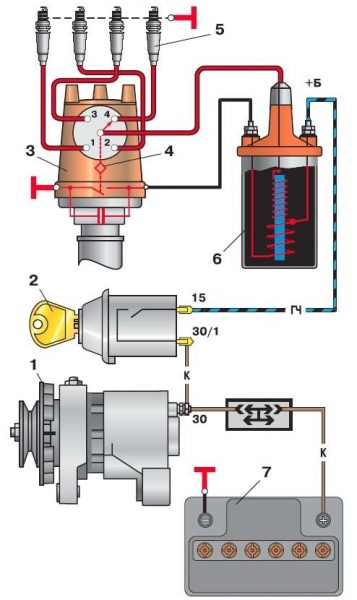
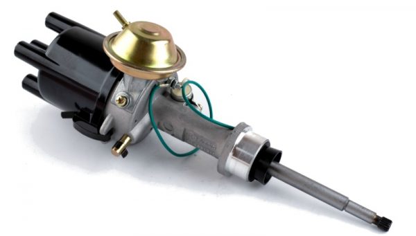
The device of the ignition system VAZ 2106
The ignition system (SZ) of a gasoline engine is designed to create and timely supply a pulsed voltage to the spark plugs.
The composition of the ignition system
The VAZ 2106 engine is equipped with a battery-contact type ignition system.
The ignition system includes:
- accumulator battery;
- switch (ignition lock with a group of contacts);
- two-winding transforming coil;
- distributor (distributor with a contact type breaker and a capacitor);
- high voltage wires;
- candles.
The ignition includes low and high voltage circuits. The low voltage circuit includes:
- battery;
- switch;
- primary winding of the coil (low voltage);
- interrupter with spark arresting capacitor.
The high voltage circuit includes:
- secondary winding of the coil (high voltage);
- distributor;
- spark plug;
- high voltage wires.
Purpose of the main elements of the ignition system
Each SZ element is a separate node and performs strictly defined functions.
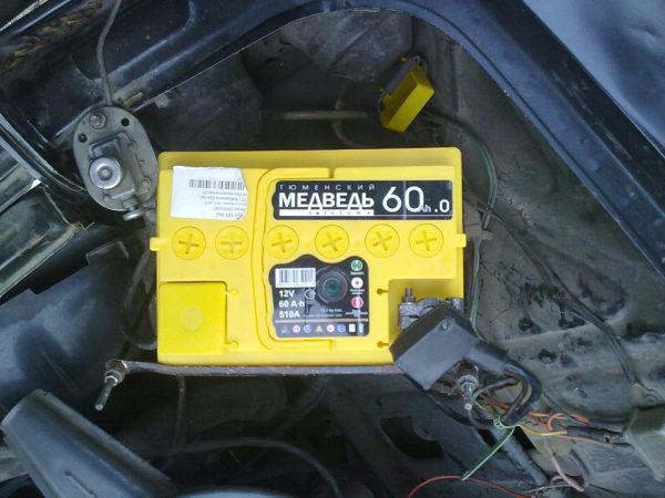
Accumulator battery
The battery is designed not only to ensure the operation of the starter, but also to power the low voltage circuit when starting the power unit. During engine operation, the voltage in the circuit is no longer supplied from the battery, but from the generator.
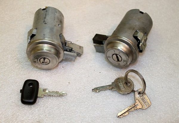
Switch
The switch is designed to close (open) the contacts of the low-voltage circuit. When the ignition key is turned in the lock, power is supplied (disconnected) to the engine.
Ignition coil
The coil (reel) is a step-up two-winding transformer. It increases the voltage of the on-board network to several tens of thousands of volts.
Distributor (distributor)
The distributor is used to distribute the impulse voltage coming from the high-voltage winding of the coil to the rotor of the device through the contacts of the top cover. This distribution is carried out by means of a runner having an external contact and located on the rotor.
Breaker
The breaker is part of the distributor and is designed to create electrical impulses in a low voltage circuit. Its design is based on two contacts - stationary and movable. The latter is driven by a cam located on the distributor shaft.
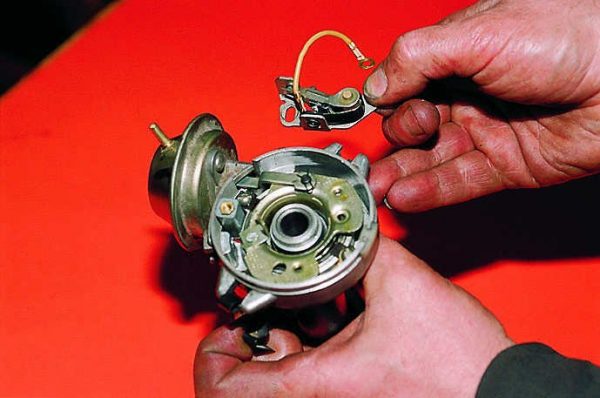
Breaker Capacitor
The capacitor prevents the formation of a spark (arc) on the contacts of the breaker if they are in the open position. One of its outputs is connected to a moving contact, the other to a stationary one.
High voltage wires
With the help of high-voltage wires, voltage is supplied from the terminals of the distributor cover to the spark plugs. All wires have the same design. Each of them consists of a conductive core, insulation and special caps that protect the contact connection.
Spark plug
The VAZ 2106 engine has four cylinders, each of which has one candle. The main function of spark plugs is to create a powerful spark capable of igniting the combustible mixture in the cylinder at a certain moment.
The principle of operation of the ignition system
When the ignition key is turned on, current begins to flow through the low voltage circuit. It passes through the contacts of the breaker and enters the primary winding of the coil, where, due to the inductance, its strength increases to a certain value. When the breaker contacts are opened, the current strength instantly drops to zero. As a result, an electromotive force arises in the high-voltage winding, which increases the voltage by tens of thousands of times. At the moment of applying such an impulse, the distributor rotor, moving in a circle, transmits voltage to one of the contacts of the distributor cover, from which voltage is supplied to the spark plug through a high-voltage wire.
The main malfunctions of the VAZ 2106 ignition system and their causes
Failures in the ignition system of the VAZ 2106 happen quite often. They can be caused by a variety of reasons, but their symptoms are almost always the same:
- inability to start the engine;
- unstable operation (triple) of the engine at idle;
- engine power reduction;
- increased gas mileage;
- occurrence of detonation.
The reasons for such situations may be:
- failure of spark plugs (mechanical damage, breakdown, resource exhaustion);
- non-compliance of the characteristics of the candles (incorrect gaps, incorrect glow number) with the requirements of the engine;
- wear of the conductive core, breakdown of the insulating layer in high-voltage wires;
- burnt contacts and (or) distributor slider;
- the formation of soot on the contacts of the breaker;
- increase or decrease in the gap between the contacts of the breaker;
- breakdown of the distributor capacitor;
- short circuit (break) in the windings of the bobbin;
- malfunctions in the group of contacts of the ignition switch.
Diagnostics of malfunctions of system of ignition
In order to save time and money, it is recommended to check the performance of the VAZ 2106 ignition system in a certain order. For diagnostics you will need:
- candle key 16 with a knob;
- head 36 with handle;
- multimeter with the ability to measure voltage and resistance;
- control lamp (regular automotive 12-volt lamp with wires connected);
- pliers with dielectric handles;
- slotted screwdriver;
- a set of flat probes for measuring gaps;
- small flat file;
- spare spark plug (known to be working).
Battery check
If the engine does not start at all, that is, when the ignition key is turned, neither the click of the starter relay nor the sound of the starter itself is heard, the test should begin with the battery. To do this, turn on the multimeter voltmeter mode with a measurement range of 20 V and measure the voltage at the battery terminals - it should not be lower than 11,7 V. At lower values, the starter will not start and will not be able to crank the crankshaft. As a result, the camshaft and the distributor rotor, which drives the breaker contact, will not start to rotate, and sufficient voltage will not form in the coil for normal sparking. The problem is solved by charging the battery or replacing it.
Circuit breaker test
If the battery is good and the relays with the starter operate normally when starting, but the engine does not start, the ignition switch should be checked. In order not to disassemble the lock, you can simply measure the voltage on the low-voltage winding of the coil. To do this, it is necessary to connect the positive probe of the voltmeter to the terminal marked with the signs "B" or "+", and the negative one - to the mass of the car. With the ignition on, the device should show a voltage equal to the voltage at the battery terminals. If there is no voltage, you should “ring out” the wire going from the contact group of the switch to the coil, and in case of a break, replace it. If the wire is intact, you will have to disassemble the ignition switch and clean the switch contacts or completely replace the contact group.
Checking the coil
After making sure that the voltage is supplied to the primary winding, you should evaluate the performance of the coil itself and check it for a short circuit. This is done in the following way.
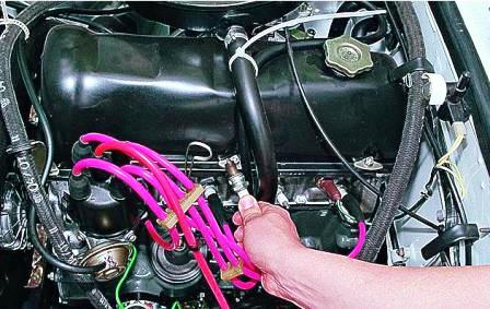
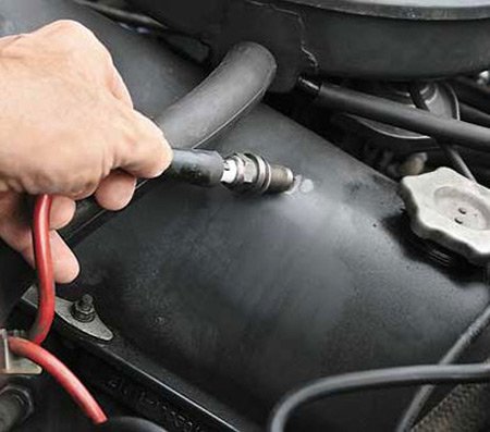
- Disconnect the cap of the central high-voltage wire from the cover of the distributor.
- Insert a candle into the cap.
- Holding the candle with pliers with dielectric handles, we connect its "skirt" with the mass of the car.
- We ask the assistant to turn on the ignition and start the engine.
- We look at the contacts of the candle. If a spark jumps between them, the coil is most likely working.
 If a stable spark is observed between the contacts of the candle, then the coil is working.
Sometimes the coil works, but the spark is too weak. This means that the voltage generated by it is not enough for normal sparking. In this case, the coil windings are checked for open and short in the following order.
- Disconnect all wires from the coil.
- We switch the multimeter to the ohmmeter mode with a measurement limit of 20 ohms.
- We connect the probes of the device to the side terminals of the coil (low voltage winding terminals). Polarity doesn't matter. The resistance of a good coil should be between 3,0 and 3,5 ohms.The resistance of both windings of a working coil should be 3,0–3,5 ohms
- To measure the resistance of a high-voltage winding on a multimeter, we change the measurement limit to 20 kOhm.
- We connect one probe of the device to the positive terminal of the coil, and the second to the central contact. The multimeter should show resistance in the range of 5,5–9,4 kOhm.
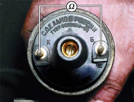
If the actual winding resistance values are noticeably different from the standard values, the coil should be replaced. In VAZ 2106 vehicles with a contact type ignition system, a B117A type reel is used.
Table: technical characteristics of the ignition coil type B117A
| Features | Indicators |
| Design | Oil-filled, two-winding, open-circuit |
| Input voltage, V | 12 |
| Low voltage winding inductance, mH | 12,4 |
| The value of the resistance of the low-voltage winding, Ohm | 3,1 |
| Secondary voltage rise time (up to 15 kV), µs | 30 |
| Pulse discharge current, mA | 30 |
| Pulse discharge duration, ms | 1,5 |
| Discharge energy, mJ | 20 |
Checking the spark plugs
The most common cause of problems in the ignition system are candles. Candles are diagnosed as follows.
- Disconnect high voltage wires from spark plugs.
- Using a candle wrench with a knob, unscrew the spark plug of the first cylinder and inspect it for damage to the ceramic insulator. Particular attention should be paid to the condition of the electrodes. If they are covered with black or white soot, you need to subsequently check the power system (black soot indicates too rich fuel mixture, white - too poor).To unscrew the VAZ 2106 spark plugs, you need a 16 socket wrench with a knob
- We insert the candle into the cap of the high-voltage wire going to the first cylinder. Holding the candle with pliers, we connect its “skirt” with the mass. We ask the assistant to turn on the ignition and run the starter for 2-3 seconds.The spark between the spark plug electrodes should be blue.
- We evaluate the spark between the electrodes of the candle. It should be stable and blue in color. If the spark intermittently disappears, has a red or orange color, the candle should be replaced.
- In the same way, we check the rest of the candles.
The engine may be unstable due to an incorrectly set gap between the electrodes of the spark plugs, the value of which is measured using a set of flat probes. The gap value regulated by the manufacturer for the VAZ 2106 with contact type ignition is 0,5–0,7 mm. If it goes beyond these limits, the gap can be adjusted by bending (bending) the side electrode.
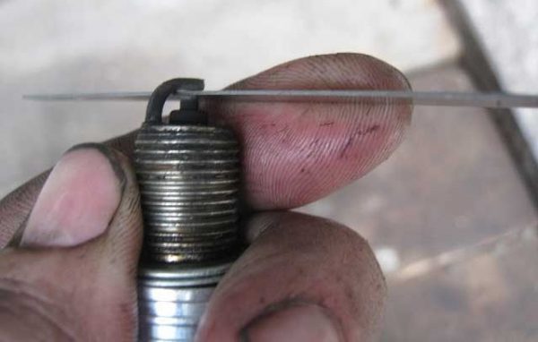
Table: main characteristics of spark plugs for the VAZ 2106 engine
| Features | Indicators |
| The gap between the electrodes, mm | 0,5 – 0,7 Feet |
| heat indicator | 17 |
| Thread type | M14 / 1,25 |
| Thread height, mm | 19 |
For VAZ 2106, when replacing, it is recommended to use the following candles:
- A17DV (Engels, Russia);
- W7D (Germany, BERU);
- L15Y (Czech Republic, BRISK);
- W20EP (Japan, DENSO);
- BP6E (Japan, NGK).
Checking high voltage wires
First, the wires should be inspected for damage to the insulation and observe them in the dark with the engine running. In the event of a breakdown of any of the wires in the engine compartment, sparking will be noticeable. In this case, the wires need to be replaced, preferably all at once.
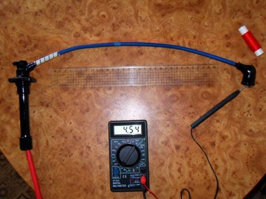
When checking wires for wear of a conductive core, its resistance is measured. To do this, the probes of the multimeter are connected to the ends of the core in ohmmeter mode with a measurement limit of 20 kOhm. Serviceable wires have a resistance of 3,5–10,0 kOhm. If the measurement results are outside the specified limits, it is recommended to replace the wires. For replacement, you can use products from any manufacturer, but it is better to give preference to companies such as BOSH, TESLA, NGK.
Rules for connecting high-voltage wires
When installing new wires, you should be very careful not to confuse the order of their connection to the distributor cover and to the candles. Usually the wires are numbered - the number of the cylinder to which it should go is indicated on the insulation, but some manufacturers do not. If the connection sequence is violated, the engine will not start or will become unstable.
To avoid errors, you need to know the sequence of operation of the cylinders. They work in this order: 1-3-4-2. On the cover of the distributor, the first cylinder is necessarily indicated by the corresponding number. Cylinders are numbered sequentially from left to right.
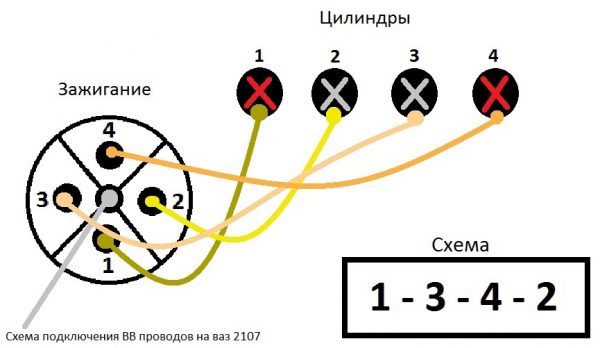
The wire of the first cylinder is the longest. It connects to terminal "1" and goes to the candle of the first cylinder on the left. Further, clockwise, the third, fourth and second cylinders are connected.
Checking the slider and distributor contacts
Diagnostics of the VAZ 2106 ignition system involves a mandatory check of the slider and distributor cover contacts. If for one reason or another they burn out, the power of the spark can noticeably decrease. No tools are required for diagnosis. It is enough to disconnect the wires from the distributor cover, unfasten the two latches and remove it. If the internal contacts or the slider have slight signs of burning, you can try to clean them with a needle file or fine-grained sandpaper. If they are badly burnt, the lid and slider are easier to replace.
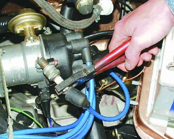
Breaker Capacitor Test
To check the health of the capacitor, you will need a test lamp with wires. One wire is connected to the "K" contact of the ignition coil, the other - to the wire going from the capacitor to the breaker. Then, without starting the engine, the ignition is turned on. If the lamp lights up, the capacitor is defective and must be replaced. The VAZ 2106 distributor uses a capacitor with a capacity of 0,22 microfarads, designed for voltages up to 400 V.
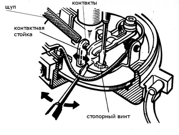
Setting the angle of the closed state of the breaker contacts
The angle of the closed state of the breaker contacts (UZSK) is, in fact, the gap between the breaker contacts. Due to constant loads, it goes astray over time, which leads to disruption of the sparking process. The UZSK adjustment algorithm is as follows:
- Disconnect the high voltage wires from the cover of the distributor.
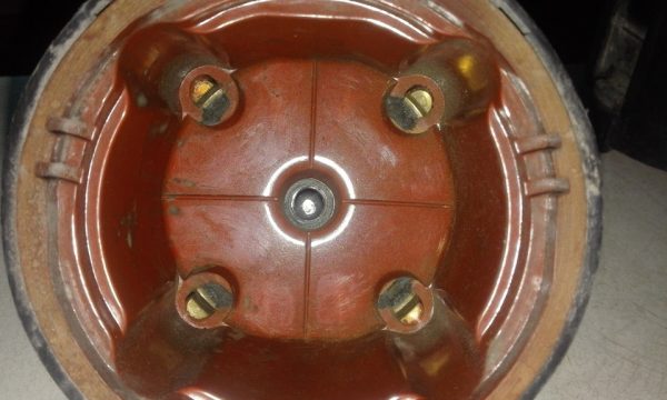
- Unfasten the two latches that secure the cover. We remove the cover.The cover of the distributor is fastened with two latches
- Unscrew the two screws securing the slider with a slotted screwdriver.
- Let's take the runner.The distributor slider is attached with two screws
- We ask the assistant to turn the crankshaft by the ratchet until the moment when the cam of the interrupter is in a position where the contacts will diverge as much as possible.
- If soot is found on the contacts, we remove it with a small needle file.
- With a set of flat probes we measure the distance between the contacts - it should be 0,4 ± 0,05 mm.
- If the gap does not correspond to this value, loosen the two screws fixing the contact post with a slotted screwdriver.
- By shifting the stand with a screwdriver, we achieve the normal size of the gap.
- Tighten the screws of the contact rack.The gap between the breaker contacts should be 0,4 ± 0,05 mm
After adjusting the UZSK, the ignition timing is always lost, so it should be set before the start of the distributor assembly.
Video: setting the gap between the breaker contacts

Ignition timing adjustment
The moment of ignition is the moment when a spark occurs on the electrodes of the candle. It is determined by the angle of rotation of the crankshaft journal with respect to the top dead center (TDC) of the piston. The ignition angle has a significant effect on the operation of the engine. If its value is too high, the ignition of the fuel in the combustion chamber will begin much earlier than the piston reaches TDC (early ignition), which can lead to detonation of the fuel-air mixture. If sparking is delayed, this will lead to a decrease in power, overheating of the engine and an increase in fuel consumption (retarded ignition).
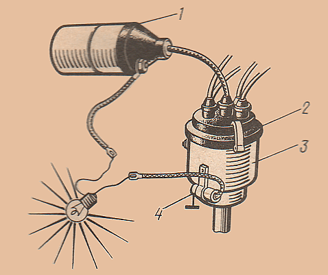
The ignition timing on the VAZ 2106 is usually set using a car strobe. If there is no such device, you can use a test lamp.
Setting the ignition timing with a stroboscope
To adjust the ignition timing you will need:
- car stroboscope;
- key on 13;
- a piece of chalk or a correction pencil for printed text.
The installation process itself is carried out in the following order:
- We start the car engine and warm it up to operating temperature.
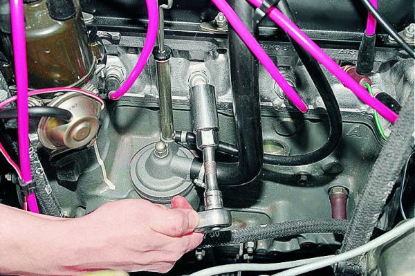
- Disconnect the hose from the vacuum corrector located on the distributor housing.
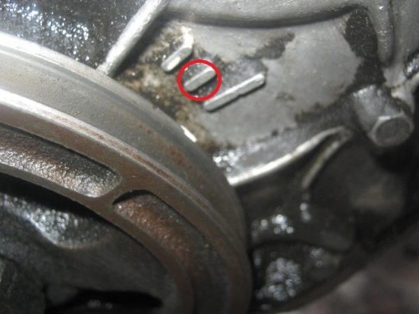
- We find three marks (low tide) on the right engine cover. We are looking for the middle mark. To make it better visible in the strobe beam, mark it with chalk or a correction pencil.When setting the ignition timing with a strobe, you need to focus on the middle mark
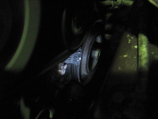
- We find an ebb on the crankshaft pulley. We put a mark on the generator drive belt above the ebb with chalk or a pencil.
- We connect the stroboscope to the on-board network of the car in accordance with the instructions for its operation. It usually has three wires, one of which is connected to the “K” terminal of the ignition coil, the second to the negative terminal of the battery, and the third (with a clip at the end) to the high-voltage wire going to the first cylinder.
- We start the engine and check if the strobe is working.
- We combine the strobe beam with the mark on the engine cover.
- Look at the mark on the alternator belt. If the ignition is set correctly, both marks in the strobe beam will match, forming a single line.When aiming the stroboscope, the marks on the engine cover and the alternator belt must match
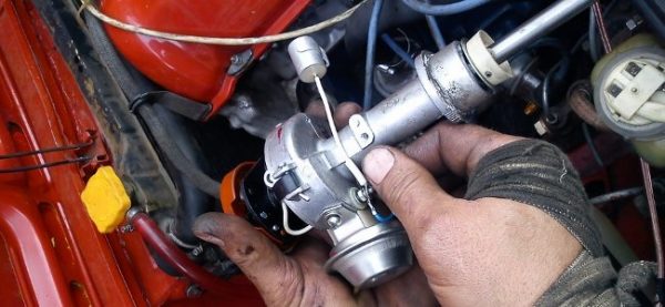
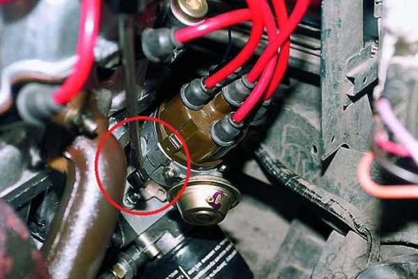
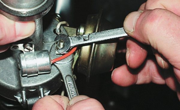
- If the marks do not match, turn off the engine and use a 13 key to unscrew the nut that secures the distributor. Turn the distributor 2-3 degrees to the right. We start the engine again and see how the position of the marks on the cover and belt has changed.The distributor is mounted on a stud with a nut
- We repeat the procedure, rotating the distributor in different directions until the marks on the cover and the belt in the strobe beam coincide. At the end of the work, tighten the distributor mounting nut.
Video: ignition adjustment using a stroboscope

Setting the ignition timing with a control light
To adjust the ignition with a lamp, you will need:
- the control lamp itself;
- head 36 with handle;
- key on 13;
- candle wrench 16 with a knob.
The order of work is as follows:
- With a head of 36, thrown over the ratchet of the crankshaft pulley, we scroll the shaft until the mark on the pulley aligns with the ebb on the cover. When using gasoline with an octane rating of 92 or higher, the mark on the pulley should be aligned with the middle ebb. If the octane number is less than 92, the mark is placed opposite the last (long) low tide.
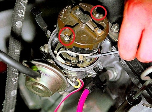
- We check whether the distributor is installed correctly in this position. We unfasten the latches and remove the cover of the distributor. The outer contact of the distributor slider should be directed to the spark plug of the first cylinder.When aligning the marks on the engine cover and the crankshaft pulley, the outer contact of the slider must be directed to the spark plug of the first cylinder
- If the slider is displaced, use a 13 key to unscrew the nut fastening the distributor, lift it up and, turning it, set it to the desired position.
- We fix the distributor without tightening the nut.
- We connect one wire of the lamp to the coil contact connected to the low-voltage output of the distributor. We close the second wire of the lamp to ground. If the breaker contacts are not open, the lamp should light up.
- Without starting the engine, turn on the ignition.
- We fix the distributor rotor by turning it all the way clockwise. Then we turn the distributor itself in the same direction until the position at which the light goes out.
- We return the distributor a little back (counterclockwise) until the light comes on again.
- In this position, we fix the distributor housing by tightening its fastening nut.
- We assemble the distributor.
Video: ignition adjustment with a light bulb

Setting the ignition by ear
If the valve timing is set correctly, you can try to set the ignition by ear. This is done in the following way.
- We warm up the engine.
- We leave on a flat section of the track and accelerate to 50-60 km / h.
- We switch to fourth gear.
- Press the accelerator pedal hard all the way down and listen.
- With the ignition set correctly, at the moment the pedal is pressed, a short-term (up to 3 s) detonation should occur, accompanied by the ringing of piston fingers.
If the detonation lasts more than three seconds, the ignition is early. In this case, the distributor housing is rotated a few degrees counterclockwise, and the verification procedure is repeated. If there is no detonation at all, the ignition is later, and the distributor housing must be turned clockwise before repeating the test.
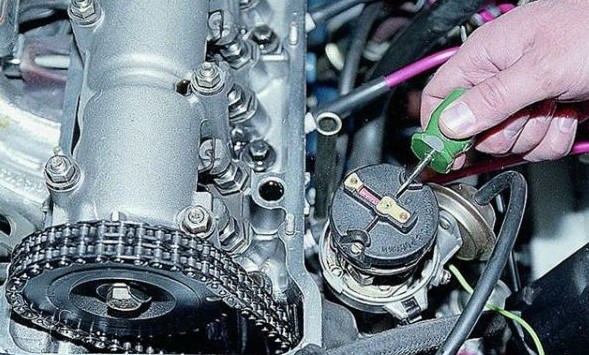
Contactless ignition VAZ 2106
Some owners of the VAZ 2106 are replacing the contact ignition system with a contactless one. To do this, you have to replace almost all elements of the system with new ones, but as a result, ignition is simpler and more reliable.
There is no interrupter in the contactless ignition system, and its function is performed by a Hall sensor built into the distributor and an electronic switch. Due to the lack of contacts, nothing gets lost here and does not burn, and the resource of the sensor and switch is quite large. They can fail only due to power surges and mechanical damage. In addition to the absence of a breaker, a contactless distributor is no different from a contact one. Setting the gaps on it is not carried out, and setting the ignition moment is no different.
A contactless ignition kit will cost about 2500 rubles. It includes:
- distributor with Hall sensor;
- ignition coil, the design of which differs from the design of the coil for contact ignition;
- electronic switch.In a contactless ignition system, the function of the interrupter is performed by a switch and a Hall sensor
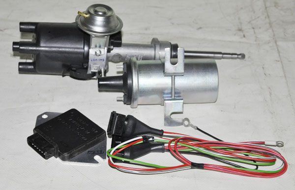
All of these parts can be purchased separately. In addition, new candles (with a gap of 0,7–0,8 mm) will be required, although old ones can be adapted. Replacing all elements of the contact system will take no more than an hour. In this case, the main problem is finding a seat for the switch. The new coil and distributor are easily installed in place of the old ones.
Contactless ignition with microprocessor switch
Owners of the VAZ 2106, who have knowledge in the field of electronics, sometimes install contactless ignition with a microprocessor switch on their cars. The main difference between such a system from a contact and a simple non-contact one is that no adjustments are needed here. The switch itself regulates the advance angle, referring to the knock sensor. This ignition kit includes:
- microprocessor switch;
- contactless distributor;
- ignition coil;
- knock sensor;
- connecting wires.After installing the microprocessor ignition, there is no need to adjust it
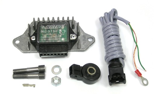
Installing and configuring such a system is quite simple. The main problem will be finding the best place to mount the knock sensor. According to the instructions that come with the microprocessor system, the sensor must be installed on one of the extreme studs of the intake manifold, that is, on the stud of the first or fourth cylinders. The choice is up to the car owner. The first cylinder stud is preferable, as it is easier to get to. To install the sensor, you do not need to drill the cylinder block. It will only be necessary to unscrew the stud, replace it with a bolt of the same diameter and with the same thread, put the sensor on it and tighten it. Further assembly is carried out according to the instructions.
The cost of a microprocessor ignition kit is about 3500 rubles.
Setting up, maintaining and repairing the VAZ 2106 ignition system is quite simple. It is enough to know the features of its device, have a minimum set of locksmith tools and carefully follow the recommendations of specialists.

